
Summary of Contents for Mauell ME 3011b
- Page 1 Alarm Systems SERIAL PRODUCTS Digital Alarm Annunciator ME 3011b Instruction Manual Manual ME3011b_E_v0707_Pre.doc 1/50...
-
Page 2: Table Of Contents
1 – Information and Technical Data Introduction Warranty Installation Operation Principles Technical Data Modularity and arrangements Dimensions Panel Mounting Product Identification Product Code Front display engraving/printing Signaling sequences Special Options 2 – Product Description CM-0x – Master CPU’s Module CM-03 – Master CPU 2v x 4h CM-04 –... - Page 3 SM-02 position on 16h enclosure Configuration modes 4 - e.Tool ME3011 config - Configuration via serial interface 5 - Configuration via keyboard 6 – Communication Protocol - Serial Modbus RTU 7- e.Tool ME2011 view This manual is subject to changes without previous advice Revision Control Author Version/Rev...
-
Page 4: Introduction
INTRODUCTION Dear Customer, Mauell thanks you for trusting us on choosing our products. It is a pleasure to provide you all necessary information on the newest member of its Mauell annunciator family. This manual presents all information needed to connect and power up the annunciator, as well as instructions for configuring it. -
Page 5: Installation
If so, it is necessary to contact immediately the receiving sector of your company, which may notify your insurance company and Mauell so the involved parts may adopt the necessary measures to repair the damages and to initiate the reimbursement of eventual expenses. -
Page 6: Operation Principles
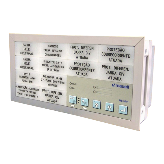
The ME 3011 annunciator, the new member of Mauell annunciator family, keeps one of the most important characteristics of ME 3010 series, which is the modularity of the alarm windows. The processing fundament of the alarm signs is now carried out through latest generation micro controllers, with high performance RISC architecture. -
Page 7: Technical Data
TECHNICAL DATA 1 - Supply Voltage 1.1 PS-05 Power Supply 24 Vdc ± 20% Input: 19 to 264 Vdc and / or 90 to 264 Vac 1.2 PS-06 Power Supply (Option) Auxiliary field output: 24Vdc / 0,75A 1.3 Special Option PSFD Power Supply Fault Detector (PSFD) for Vdc and/or Vac 1.4 Note: All power supplies are integrated into the annunciator... - Page 8 TECHNICAL DATA 5 - Event Register (Option) Events 1000, with Time Stamp Resolution 1 ms, samples 2,5 ms Interfaces RS232C or RS485 Protocols Modbus RTU (Slave) 6 - Visualization Light Indication Back light Available in red, yellow, green, white and blue colors Ultra Bright Back light Available in red, yellow, green, white and blue colors Available in red, yellow, green, white and blue colors, on sockets...
-
Page 9: Modularity And Arrangements
MODULARITY AND ARRANGEMENTS The minimum configuration possible for the annunciator is a central module with 4 alarm points, and dimension of 2V x 4H or 4V x 2H. (see shaded portion on lower right corner of diagram below) Expansion modules can be added to this central unit, with 4 or 8 alarm points each, always in 2V x 2H or 2V x 4H modularity basis. -
Page 10: Dimensions
DIMENSIONS Cutout table [height (h) x width (v)] mm h (x) Points x 209 x 401 x 593 x 785 113 x 113 113 x 209 113 x 305 113 x 401 113 x 497 113 x 593 113 x 689 113 x 785 161 x 113 161 x 209... -
Page 11: Panel Mounting
PANEL MOUNTING Each ME 3011 is shipped with a certain amount of panel clamps according the annunciator’s size. 1 – Locate the panel clamps inside the packing box and prepare the mounting 2 – Insert the annunciator into the cutout 3 –... -
Page 12: Product Identification
Serial #: 70515300 24 Vdc Field: 19-264 Vdc / 90-264 Vac Power Supply: Helmut Mauell do Brasil www.mauell.com.br Indústria Brasileira / Made in Brazil / Fabriqué au Brésil 1.1 Code Product code with 15 digits 1.2 Serial# Product serial number YY/9999, where YY is the year and 9999 is a sequential number 1.3 FW:... -
Page 13: Product Code
PRODUCT CODE Go to the ME3011b Codification: ME3011b - Code 012 28 FE 44 512 00 1 ME3011b BL Alarm Annunciator - 12 Alarm Points - 2V x 8H: Power Supply 19-264 Vdc / 90-264 Vac - PSFD at Keyboard, BL 5 Colors, 110/125 Vdc Field Voltage with RRO, RS232C (R) + RS485 + ER + GPS Sync, Modbus RTU (Slave) + ER, with Engraving and Special Options. - Page 14 FRONT DISPLAY INSCRIPTIONS 1 – Low Relief Engraving 1.1 – Back Light Display LB 24 x 48 – White Translucent - Code: 83.53.002 Character height = 3 mm Maximum number of characters per line = 19 Maximum number of lines = 4 ABCDEFGHJKLMNOPRSTU ABCDEFGHJKLMNOPRSTU ABCDEFGHJKLM...
-
Page 15: Signaling Sequences
SIGNALING SEQUENCES The ME 3011 can be configured in order to comply with 16 signaling sequence. Among them the most important are the following: (ISA-S18.1) ISA-RP 18.1/ (A-5) (A-4) (R-8) (F1A) (F1M) ISA1/ , ISA-1A/ , ISA-1B/ , ISA-2A/ , ISA-2C/ , ISA-4A/ , ISA-4AR/ etc. -
Page 16: Special Options
SPECIAL OPTIONS 1 – Light display with more than one color In this case, the quantity and position for each color must be request by the costumer. For LED Display – up to 3 colors (red / yellow / green) For Back Light Display –... - Page 17 PRODUCT DESCRIPTION - CM-0x MODULES 1 - CM-0x - “Central Module” - Master CPU Module with 4 alarm points Master CPU module is responsible for slave module management, man-machine interface for alarm acknowledge, annunciator configuration, sound signaling, light signaling and its own operating status. Annunciator has a RS 485 interface with Modbus RTU protocol as option, allowing interconnection of several...
- Page 18 1.2 PRODUCT DESCRIPTION - CM-04 MODULE Vdc Fault Vac Fault RS 485 balancing: Extract the tile of alarm point number 3 and set the jumpers as follows: • JP1 and JP2 closed for the last annunciator on the network. • JP1 and JP2 open for all intermediary annunciators on the network.
-
Page 19: Product Description
PRODUCT DESCRIPTION - CM-0x MODULES CM-03 and CM-04 Module Connector Identification Line Identification Connector Term. Desc. Function CM-03 CM-04 CM-03 CM-04 Vac Power Supply X11 - CX1 - 1 X11 - CX1 - 1 Vac Power Supply X11 - CX1 - 2 X11 - CX1 - 2 Shield Shield... - Page 20 2 - SM-02 - “Slave Module” - CPU Slave Module with 8 alarm points Each Slave CPU Module is able to control up to 64 alarm points, and is used if number of alarm points exceeds 60. For configurations from 62 to 128 points one Slave CPU Module is used, from 130 to 188 two Modules, and from 190 to 252 three Modules.
-
Page 21: Em-0X - Expansion Modules
PRODUCT DESCRIPTION - EM-0x EXPANSION MODULES 3 - EM-0x - Expansion Module. 3.1 - EM-02 - Expansion Module with 8 alarm points, arrangement 2v x 4h. Each expansion modules provides 8 alarm points, used together with CPUs. Front view OPTIONS Rear view EM-02 - Expansionn Module Connectors Identification Line... - Page 22 PRODUCT DESCRIPTION - EM-0x EXPANSION MODULES 3.2 - EM-03 – Expansion Module with 8 alarm points, arrangement 4v x 2h Front view OPTIONS Rear view EM-03 - Expansion Module Connectors Identification Line Connector Term. Obs. Function Identificacion Input + Alarm Input 1 X..
- Page 23 PRODUCT DESCRIPTION - EM-0x EXPANSION MODULES 3.3- EM-04 – Expansion Module with 4 alarm points, arrangement 2v x 2h OPTIONS EM-04 - Expansion Module Connectors Identification Line Connector Term. Obs. Function Identificacion Input + Alarm Input 1 X.. - C1 - 1 Input + Alarm Input 2 X..
-
Page 24: Functions
KEYBOARD FUNCTION DESCRIPTION 1 – Keyboard Functions Green LED continuously on indicates system operative Blinking Green LED indicates system operative in Sleep Mode (SLM) PSFD Yellow LED for Vdc power supply fault and Orange LED for Vac power supply fault indication, if requested. Vdc Fault Red LED on, indicates system Vac Fault... - Page 25 KEYBOARD FUNCTION DESCRIPTION 1.5 – Functional Test (FT) Functional test is performed through TL button on CPU module front panel, which simulates an alarm condition in all points when activated, according to pre-configured sequence in equipment. Note About Light and Functional Tests: Light test button (TL) must be configured according to desired Function: either Light test, or Function test.
- Page 26 GENERAL FUNCTION DESCRIPTION 2 – General functions 2.1 – Sound Signal Annunciator has a “buzzer”, which can be configured to generate different sounds (continuous, intermittent and two-tone) and disabled. For connecting external buzzer, potential-free terminals are available on the rear panel for external buzzer, with 30W of capacity.
-
Page 27: Power Supply
INSTALLATION – ANNUNCIATOR POWER SUPPLY 1 – ME3011b power supply 1.1 – Annunciator standard supply voltage is 24 Vdc For other voltages, the following power supplies can be incorporated into the annunciator: 2 – Redundant voltage supply with 19 to 264 Vdc and/or 90 to 264 Vac The quantity is the same as of Master and Slave CPUs used in annunciator configuration. -
Page 28: Remote Push-Button
INSTALLATION - INPUTS 1 – Field Inputs Field inputs are galvanically isolated by opto couplers and protected against surges, with a common signal per alarm group (4 points for Cm-0x Module, 8 points for EM-02, EM-03 and SM-02 , 4 points for EM-04), and can be provided optionally with repeat relays. -
Page 29: Gps Synchronization (Option)
INSTALLATION - INPUTS 3 – GPS synchronization (Option) Via connector CX9 from the CM-0x CPUs In this case, the blink synchronism is performed internally via Modbus. Manual ME3011b_E_v0707_Pre.doc 29/50... -
Page 30: Outputs
INSTALLATION - OUTPUTS 3 – Field Voltage Supply 24 Vdc Annunciator has, regardless main voltage supply or field voltage, one 24 Vdc / 1A output for field contacts in CM-0x and SM-02 modules. It is recommended the use of a fast 1A fuse at +24Vdc 4 –... - Page 31 INSTALLATION - OUTPUTS 6 – Repeater Relays output (Option) Relay with 1 potential-free NO contact per alarm input, where the relays coil is actuated due the input voltage. That means, if the annunciator fail, the alarms continues to be repeated. For field voltages over 125Vdc and Vac voltages, this option is not available.
- Page 32 7 – Repeater relays for power fault detection (Option) The Vdc fault detection can be indicated at the alarm point 2 or at the yellow led from the keyboard. The Vac fault detection can be indicated at the alarm point 4 or at the orange led from the keyboard. If the PSFD indication are the alarm points 2 and 4, there are no relay on the connector C2-2 and C2-4.
- Page 33 INSTALLATION - OUTPUTS 8 – Flashing Synchronization Option This function is performed due the CPUs CM-0x CX9 connector. The tCX9 – terminal 1 of the synchronizing annunciator must be connected to the CX9-terminal 1 from the other annunciators. The CX2 –terminal 2 (-24Vdc) from all annunciators must be connected. Manual ME3011b_E_v0707_Pre.doc 33/50...
-
Page 34: Recommendations
RECOMMENDATIONS Recommendations: Control and load cables must be ad equally separated, if possible in separated cable trays. If there are crossing lines, try to mount it on perpendicular crossing. It is recommended that power line filters be installed at the cabinet input to achieving successful filtering of electromagnetic interference, this filter acts as a barrier between polluted energy and clean energy goes into the cabinet. - Page 35 INPUT LEVELS Manual ME3011b_E_v0707_Pre.doc 35/50...
-
Page 36: Connection Diagram Examples
CONNECTION DIAGRAM EXAMPLES 1 –Standard, Front view Connector Identification I - X..-C_-N I - X25-C1-1 I - X25-C1-2 I - X25-C1-3 I - X25-C1-4 I - X15-C1-1 I - X15-C1-2 I - X15-C1-3 I - X15-C1-4 I - Alarm Input I - X25-C1-5 I - X25-C1-6 I - X25-C1-7... - Page 37 CONNECTION DIAGRAM EXAMPLES 2 –Standard, rear view Manual ME3011b_E_v0707_Pre.doc 37/50...
- Page 38 CONNECTION DIAGRAM EXAMPLES - Connection diagram with RRO and power fault indication, Vdc at alarm point 2 or yellow led on the keyboard end/or Vac fault at alarm point 4 or orange led on the keyboard Front view Connector Identification I1- X25-C1-1 I2 - X25-C1-2 I3 - X25-C1-3...
- Page 39 CONNECTION DIAGRAM EXAMPLES Rear view Manual ME3011b_E_v0707_Pre.doc 39/50...
-
Page 40: Terminal Identification
TERMINAL IDENTIFICATION FOR ENCLOSURES WITH CM-03 MODULE – REAR VIEW Number of horizontal points (h) X 1C X 2C y = 12 X 1B X 2B y = 11 X 1A X 2A X 3A y = 10 X 19 X 29 X 39 y = 9... - Page 41 TERMINAL IDENTIFICATION FOR ENCLOSURES WITH CM-03 MODULE – FRONT VIEW Number of horizontal points (h) X 2C X 1C y = 12 X 2B X 1B y = 11 X 2A X 2A X 1A y = 10 X 39 X 29 X 19 y = 9...
- Page 42 TERMINAL IDENTIFICATION FOR ENCLOSURES WITH CM-04 MODULE – REAR VIEW Number of horizontal Points X 22 y = 12 X 21 y = 11 X 20 y = 10 X 19 y = 9 X 18 y = 8 X 17 y = 7 X 16 y = 6...
- Page 43 TERMINAL IDENTIFICATION FOR ENCLOSURES WITH CM-04 MODULE –FRONT VIEW Number of horizontal Points X 22 y = 12 X 21 y = 11 X 20 y = 10 X 19 y = 9 X 18 y = 8 X 17 y = 7 X 16 y = 6...
-
Page 44: New Arrangements
NEW ARRANGEMENTS – REAR VIEW 20v x 2h 18v x 2h 16v x 2h EM-03 EM-04 14v x 2h 12v x 2h EM-03 EM-03 EM-03 EM-04 10v x 2h 8v x 2h EM-03 EM-03 EM-03 EM-03 EM-03 EM-04 6v x 2h 4v x 2h EM-03 EM-03... -
Page 45: Sm-02 Module Positions
SM-02 MODULE POSITION ON 4h ENCLOSURE – REAR VIEW 24v x 4h 22v x 4h EM-02 20v x 4h EM-02 EM-02 18v x 4h EM-02 EM-02 EM-02 16v x 4h SM-02 SM-02 SM-02 SM-02 14v x 4h EM-02 EM-02 EM-02 EM-02 EM-02 EM-02... - Page 46 SM-02 MODULE POSITION ON 8h ENCLOSURE – REAR VIEW 24v x 8h 22v x 8h EM-02 EM-02 20v x 8h EM-02 EM-02 EM-02 EM-02 18v x 8h EM-02 EM-02 EM-02 EM-02 EM-02 EM-02 SM-02 EM-02 SM-02 EM-02 SM-02 EM-02 SM-02 EM-02 EM-02 EM-02...
- Page 47 SM-02 MODULE POSITION ON 12h ENCLOSURE – REAR VIEW 20v x 12h 18v x 12h EM-02 EM-02 EM-02 16 x 12h SM-02 SM-02 EM-02 EM-02 EM-02 EM-02 EM-02 EM-02 EM-02 EM-02 EM-02 EM-02 EM-02 EM-02 EM-02 EM-02 EM-02 EM-02 EM-02 EM-02 EM-02 EM-02...
- Page 48 SM-02 MODULE POSITION ON 16h ENCLOSURE – REAR VIEW 16v x 16h 14v x 16h EM-02 EM-02 EM-02 EM-02 SM-02 EM-02 EM-02 EM-02 SM-02 EM-02 EM-02 EM-02 EM-02 EM-02 EM-02 EM-02 EM-02 EM-02 EM-02 EM-02 SM-02 EM-02 EM-02 EM-02 SM-02 EM-02 EM-02 EM-02...
- Page 49 CONFIGURATION MODES The ME 3011b Annunciator provides two ways for parameter configuration. 1 – Via Serial Interface e.Tool ME3011- config By means of RS232C serial interface, using program. Detailed instructions you find at Configuration via serial interface - e.Tool ME3011 config Manual Interface RS232C - Cable C S-02 - 5, 10 or 15m The latest e.Tool ME3011- config software can be downloaded from our site:...
- Page 50 Brazil Representatives and branches – Worldwide Helmut Mauell do Brasil Est. Estadual Salvador de Leone, 2998 Abu Dhabi E.A.U. Korea 06850-000 – Itapecerica da Serra - SP Argentina Malaysia Tel.: +55 (0) 11 2117 5353 Belgium Netherlands Fax.: +55 (0) 11 2117 5354...
Need help?
Do you have a question about the ME 3011b and is the answer not in the manual?
Questions and answers