Table of Contents
Advertisement
21 - 130
AUTOMATIC TRANSMISSION - 48RE
AUTOMATIC TRANSMISSION - 48RE
. . . . . . . . . . . . . . . . . . . . . . . . 132
. . . . . . . . . . . . . . . . . . . . . . . . . . 134
TRANSMISSION . . . . . . . . . . . . . . . . . . . . . 140
TESTING . . . . . . . . . . . . . . . . . . . . . . . . . . . 140
PRESSURE TEST . . . . . . . . . . . . . . . . . . . . 141
OPERATION . . . . . . . . . . . . . . . . . . . . . . . . 144
HOUSING FLUID LEAK . . . . . . . . . . . . . . . . 144
CHARTS . . . . . . . . . . . . . . . . . . . . . . . . . . . 145
. . . . . . . . . . . . . . . . . . . . . . . . . . . . 158
. . . . . . . . . . . . . . . . . . . . . . . . 160
. . . . . . . . . . . . . . . . . . . . . . . . . . . 166
. . . . . . . . . . . . . . . . . . . . . . . . . 166
. . . . . . . . . . . . . . . . . . . . . . . . . . . 166
. . . . . . . . . . . . . . . . . . . . . . . . 174
. . . . . . . . . . . . . . . . . . . . . . . . 193
. . . . . . . . . . . . . . . . . . . . . . . . . . 193
. . . . . . . . . . . . . . . . . . . . . . . . . 194
. . . . . . . . . . . . . . . . . . . . . . . . 194
. . . . . . . . . . . . . . . . . . . . . . . . . . 194
. . . . . . . . . . . . . . . . . . . . . . . . 196
. . . . . . . . . . . . . . . . . . . . . . . . . . 196
TABLE OF CONTENTS
. . . . . . . . . . . . . . . . . . . . . 158
. . . . . . . . . . . . . 176
. . . . . . . . . . . . . . . . . . . . . 189
. . . . . . . . . . . . . . . . . . 191
. . . . . . . . . . . . . . . 195
. . . . . . 196
. . . . . . . . . . . . . . . . . . . 196
page
INCORRECT FLUID LEVEL . . . . . . . . . . . . . 201
BURNT FLUID . . . . . . . . . . . . . . . . . . . . . . . 201
CONTAMINATION . . . . . . . . . . . . . . . . . . . . 202
CHECK . . . . . . . . . . . . . . . . . . . . . . . . . . . . 202
FILTER REPLACEMENT . . . . . . . . . . . . . . . 203
FILL . . . . . . . . . . . . . . . . . . . . . . . . . . . . . . . 204
. . . . . . . . . . . . . . . . . . . . . . . . . . . . . 210
. . . . . . . . . . . . . . . . . . . . . . . . 197
. . . . . . . . . . . . . . . . . . . . . . . . . . 198
. . . . . . . . . . . . . . . . . . . . . . . . . . . . 199
. . . . . . . . . . . . . . . . . . . . . . . . 200
. . . . . . . . . . . . . . . . . . . . . . . . . . . . 201
. . . . . . . . . . . . . . . . . . . . . . . . 201
. . . . . . . . . . . . . . . . . . . . . . . . 205
. . . . . . . . . . . . . . . . . . . . . . . . . . 205
. . . . . . . . . . . . . . . . . . . . . . . . 205
. . . . . . . . . . . . . . . . . . . . . . . . . 206
. . . . . . . . . . . . . . . . . . . . . . . . . . . 207
. . . . . . . . . . . . . . . . . . . . . . . . 208
. . . . . . . . . . . . . . . . . . . . . . . . . . 208
. . . . . . . . . . . . . . . . . . . . . . . . 209
. . . . . . . . . . . . . . . . . . . . . . . . . . . 209
. . . . . . . . . . . . . . . . . . . . . . . . . 209
. . . . . . . . . . . . . . . . . . . . . . . . . . . 209
. . . . . . . . . . . . . . . . . . . . . . . . . . . . 210
. . . . . . . . . . . . . . . . . . . . . . . . 211
. . . . . . . . . . . . . . . . . . 212
. . . . . . . . . . . . . . . . . . . . . . . . 213
. . . . . . . . . . . . . . . . . . . . . . . . . . 213
. . . . . . . . . . . . . . . . . . . . . . . . 214
. . . . . . . . . . . . . . . . . . . . . . . . . . . 214
. . . . . . . . . . . . . . . . . . . . . . . . . 214
. . . . . . . . . . . . . . . . . . . . . . . . . . . 214
DR
page
Advertisement
Table of Contents

Related Manuals for Chrysler 48RE

Summary of Contents for Chrysler 48RE
-
Page 1: Table Of Contents
21 - 130 AUTOMATIC TRANSMISSION - 48RE AUTOMATIC TRANSMISSION - 48RE TABLE OF CONTENTS page page AUTOMATIC TRANSMISSION - 48RE ELECTRONIC GOVERNOR DESCRIPTION ......132 DESCRIPTION . - Page 2 AUTOMATIC TRANSMISSION - 48RE 21 - 131 OUTPUT SHAFT FRONT BEARING OPERATION ......252 REMOVAL .
-
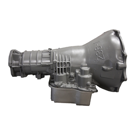
Page 3: Automatic Transmission - 48Re Description
DESCRIPTION components, in the front, rear, or overdrive planetary The 48RE (Fig. 1) is a four speed fully automatic gear set, transfer the engine power from the input transmissions with an electronic governor. The 48RE shaft through to the output shaft. - Page 4 AUTOMATIC TRANSMISSION - 48RE 21 - 133 AUTOMATIC TRANSMISSION - 48RE (Continued)
-
Page 5: Operation
21 - 134 AUTOMATIC TRANSMISSION - 48RE AUTOMATIC TRANSMISSION - 48RE (Continued) 1 - TORQUE CONVERTER 10 - OVERDRIVE CLUTCH 2 - INPUT SHAFT 11 - DIRECT CLUTCH 3 - OIL PUMP 12 - PLANETARY GEAR 4 - FRONT BAND... - Page 6 AUTOMATIC TRANSMISSION - 48RE 21 - 135 AUTOMATIC TRANSMISSION - 48RE (Continued) PARK POWERFLOW NEUTRAL POWERFLOW As the engine is running and the crankshaft is With the gear selector in the NEUTRAL position rotating, the flexplate and torque converter, which (Fig.
- Page 7 21 - 136 AUTOMATIC TRANSMISSION - 48RE AUTOMATIC TRANSMISSION - 48RE (Continued) REVERSE POWERFLOW the planet pinions is transferred to the rear annulus gear, which is splined to the output shaft. The output When the gear selector is moved into the shaft in turn rotates with the annulus gear in a REVERSE position (Fig.
- Page 8 AUTOMATIC TRANSMISSION - 48RE 21 - 137 AUTOMATIC TRANSMISSION - 48RE (Continued) FIRST GEAR POWERFLOW direction. With the rear annulus gear stationary, the rear planet rotation on the annulus gear causes the When the gearshift lever is moved into the DRIVE rear planet carrier to revolve in a counterclockwise position the transmission goes into first gear (Fig.
- Page 9 21 - 138 AUTOMATIC TRANSMISSION - 48RE AUTOMATIC TRANSMISSION - 48RE (Continued) SECOND GEAR POWERFLOW Now that the front band is holding the sun gear sta- tionary, the annulus rotation causes the front planets In DRIVE-SECOND (Fig. 7), the same elements to rotate in a clockwise direction.
- Page 10 AUTOMATIC TRANSMISSION - 48RE 21 - 139 AUTOMATIC TRANSMISSION - 48RE (Continued) DIRECT DRIVE POWERFLOW FOURTH GEAR POWERFLOW The vehicle has accelerated and reached the shift Fourth gear overdrive range is electronically con- point for the 2-3 upshift into direct drive (Fig. 8).
-
Page 11: Diagnosis And Testing Diagnosis And Testing - Automatic Transmission
21 - 140 AUTOMATIC TRANSMISSION - 48RE AUTOMATIC TRANSMISSION - 48RE (Continued) valve moves the overdrive piston into contact with VEHICLE IS DISABLED the overdrive clutch. The direct clutch is disengaged (1) Check fluid level and condition. before the overdrive clutch is engaged. The boost... -
Page 12: Diagnosis And Testing - Hydraulic Pressure Test
AUTOMATIC TRANSMISSION - 48RE 21 - 141 AUTOMATIC TRANSMISSION - 48RE (Continued) CLUTCH AND BAND APPLICATION CHART SHIFT TRANSMISSION CLUTCHES AND BANDS OVERDRIVE CLUTCHES LEVER FRONT FRONT REAR REAR OVER- OVER- DIRECT OVER- POSITION CLUTCH BAND CLUTCH BAND RUNNING DRIVE... - Page 13 21 - 142 AUTOMATIC TRANSMISSION - 48RE AUTOMATIC TRANSMISSION - 48RE (Continued) • Line pressure at accumulator port should be The rear servo and governor pressure ports are at the right rear of the transmission case. The overdrive 54-60 psi (372-414 kPa) with throttle lever forward clutch pressure port is at the left rear of the case.
- Page 14 AUTOMATIC TRANSMISSION - 48RE 21 - 143 AUTOMATIC TRANSMISSION - 48RE (Continued) (3) Have helper start and run engine at 1600 rpm (5) Secure test gauge so it can be viewed from for test. drivers seat. (4) Move transmission shift lever four detents rear- (6) Start engine and shift into D range.
-
Page 15: Diagnosis And Testing - Air Testing Transmission Clutch And Band Operation
21 - 144 AUTOMATIC TRANSMISSION - 48RE AUTOMATIC TRANSMISSION - 48RE (Continued) DIAGNOSIS AND TESTING - AIR TESTING Rear Clutch Air Test Place one or two fingers on the clutch housing and TRANSMISSION CLUTCH AND BAND apply air pressure through rear clutch apply passage. -
Page 16: Diagnosis And Testing - Diagnosis Charts
AUTOMATIC TRANSMISSION - 48RE 21 - 145 AUTOMATIC TRANSMISSION - 48RE (Continued) (4) Inspect pump bushing and converter hub. If bushing is scored, replace it. If converter hub is scored, either polish it with crocus cloth or replace converter. (5) Install new pump seal, O-ring, and gasket. - Page 17 21 - 146 AUTOMATIC TRANSMISSION - 48RE AUTOMATIC TRANSMISSION - 48RE (Continued) DIAGNOSIS CHARTS CONDITION POSSIBLE CAUSES CORRECTION HARSH ENGAGEMENT 1. Fluid Level Low. 1. Add Fluid (FROM NEUTRAL TO 2. Throttle Linkage Mis-adjusted. 2. Adjust linkage - setting may be too long.
- Page 18 AUTOMATIC TRANSMISSION - 48RE 21 - 147 AUTOMATIC TRANSMISSION - 48RE (Continued) CONDITION POSSIBLE CAUSES CORRECTION DELAYED ENGAGEMENT 1. Fluid Level Low. 1. Correct level and check for leaks. (FROM NEUTRAL TO 2. Filter Clogged. 2. Change filter. DRIVE OR REVERSE) 3.
- Page 19 21 - 148 AUTOMATIC TRANSMISSION - 48RE AUTOMATIC TRANSMISSION - 48RE (Continued) CONDITION POSSIBLE CAUSES CORRECTION NO DRIVE OR REVERSE 1. Fluid Level Low. 1. Add fluid and check for leaks if drive is (VEHICLE WILL NOT restored. MOVE) 2. Gearshift Linkage/Cable 2.
- Page 20 AUTOMATIC TRANSMISSION - 48RE 21 - 149 AUTOMATIC TRANSMISSION - 48RE (Continued) CONDITION POSSIBLE CAUSES CORRECTION NO REVERSE (D RANGES 1. Gearshift Linkage/Cable 1. Repair or replace linkage parts as Mis-adjusted/Damaged. needed. 2. Park Sprag Sticking. 2. Replace overdrive annulus gear.
- Page 21 21 - 150 AUTOMATIC TRANSMISSION - 48RE AUTOMATIC TRANSMISSION - 48RE (Continued) CONDITION POSSIBLE CAUSES CORRECTION NO KICKDOWN OR 1. Throttle Linkage Mis-adjusted. 1. Adjust linkage. NORMAL DOWNSHIFT 2. Accelerator Pedal Travel 2. Verify floor mat is not under pedal, repair Restricted.
- Page 22 AUTOMATIC TRANSMISSION - 48RE 21 - 151 AUTOMATIC TRANSMISSION - 48RE (Continued) CONDITION POSSIBLE CAUSES CORRECTION BUZZING NOISE 1. Fluid Level Low 1. Add fluid and check for leaks. 2. Shift Cable Mis-assembled. 2. Route cable away from engine and bell housing.
- Page 23 21 - 152 AUTOMATIC TRANSMISSION - 48RE AUTOMATIC TRANSMISSION - 48RE (Continued) CONDITION POSSIBLE CAUSES CORRECTION GROWLING, GRATING OR 1. Drive Plate Broken. 1. Replace. SCRAPING NOISES 2. Torque Converter Bolts Hitting 2. Dust shield bent. Replace or repair. Dust Shield.
- Page 24 AUTOMATIC TRANSMISSION - 48RE 21 - 153 AUTOMATIC TRANSMISSION - 48RE (Continued) CONDITION POSSIBLE CAUSES CORRECTION NO 4-3 DOWNSHIFT 1. Control Switch Open/Shorted. 1. Test and replace switch if faulty. WHEN CONTROL SWITCH 2. Overdrive Solenoid Connector 2. Test solenoids and replace if seized or IS TURNED OFF Shorted.
- Page 25 21 - 154 AUTOMATIC TRANSMISSION - 48RE AUTOMATIC TRANSMISSION - 48RE (Continued) CONDITION POSSIBLE CAUSES CORRECTION NO 3-4 UPSHIFT 1. O/D Switch In OFF Position. 1. Turn control switch to ON position. 2. Overdrive Circuit Fuse Blown. 2. Replace fuse. Determine why fuse failed and repair as necessary (i.e., shorts or...
- Page 26 AUTOMATIC TRANSMISSION - 48RE 21 - 155 AUTOMATIC TRANSMISSION - 48RE (Continued) CONDITION POSSIBLE CAUSES CORRECTION SLIPS IN OVERDRIVE 1. Fluid Level Low. 1. Add fluid and check for leaks. FOURTH GEAR 2. Overdrive Clutch Pack Worn. 2. Remove overdrive unit and rebuild clutch pack.
- Page 27 21 - 156 AUTOMATIC TRANSMISSION - 48RE AUTOMATIC TRANSMISSION - 48RE (Continued) CONDITION POSSIBLE CAUSES CORRECTION NO START IN PARK OR 1. Gearshift Linkage/Cable 1. Adjust linkage/cable. NEUTRAL Mis-adjusted. 2. Neutral Sense Wire Open/Cut. 2. Check continuity with test lamp. Repair as required.
- Page 28 AUTOMATIC TRANSMISSION - 48RE 21 - 157 AUTOMATIC TRANSMISSION - 48RE (Continued) CONDITION POSSIBLE CAUSES CORRECTION OIL LEAKS. 1. Fluid Lines and Fittings Loose/ 1. Tighten fittings. If leaks persist, replace Leaks/Damaged. fittings and lines if necessary. 2. Fill Tube (where tube enters case) 2.
-
Page 29: Standard Procedure - Aluminum Thread Repair
21 - 158 AUTOMATIC TRANSMISSION - 48RE AUTOMATIC TRANSMISSION - 48RE (Continued) STANDARD PROCEDURE - ALUMINUM (4) Disconnect and lower or remove necessary exhaust components. THREAD REPAIR (5) Remove engine-to-transmission struts. Damaged or worn threads in the aluminum trans- (6) Remove starter motor. (Refer to 8 - ELECTRI-... - Page 30 AUTOMATIC TRANSMISSION - 48RE 21 - 159 AUTOMATIC TRANSMISSION - 48RE (Continued) (14) Disconnect throttle valve cable from transmis- sion bracket and throttle valve lever. (15) On 4X4 models, disconnect shift rod from transfer case shift lever. (16) Support rear of engine with safety stand or jack.
-
Page 31: Disassembly
21 - 160 AUTOMATIC TRANSMISSION - 48RE AUTOMATIC TRANSMISSION - 48RE (Continued) DISASSEMBLY (7) Remove filter from valve body (Fig. 18). Keep filter screws separate from other valve body screws. (1) Clean exterior of transmission with suitable Filter screws are longer and should be kept with fil- solvent or pressure washer. - Page 32 AUTOMATIC TRANSMISSION - 48RE 21 - 161 AUTOMATIC TRANSMISSION - 48RE (Continued) (10) Remove valve body assembly. Push valve body harness connector out of case. Then work park rod and valve body out of case (Fig. 20). Fig. 22 Front Band Lever Pin Access Plug...
- Page 33 21 - 162 AUTOMATIC TRANSMISSION - 48RE AUTOMATIC TRANSMISSION - 48RE (Continued) (b) Remove oil pump bolts. (16) Loosen front band adjusting screw until band (c) Thread Slide Hammer Tools C-3752 into is completely loose. threaded holes in flange of oil pump housing (Fig.
- Page 34 AUTOMATIC TRANSMISSION - 48RE 21 - 163 AUTOMATIC TRANSMISSION - 48RE (Continued) (18) Squeeze front band together slightly and slide (20) Remove front band reaction pin and lever. band over front clutch retainer and out of case (Fig. Start pin through lever and out of case bore with 28).
- Page 35 21 - 164 AUTOMATIC TRANSMISSION - 48RE AUTOMATIC TRANSMISSION - 48RE (Continued) (22) Remove thrust plate from intermediate shaft hub (Fig. 32). (23) Remove intermediate shaft-planetary geartrain assembly (Fig. 33). (24) Loosen rear band locknut and loosen adjust- ing screw 3-4 turns.
- Page 36 AUTOMATIC TRANSMISSION - 48RE 21 - 165 AUTOMATIC TRANSMISSION - 48RE (Continued) (27) Note that overrunning clutch race will remain on splines of low-reverse drum after removal (Fig. 36). The race is a permanent press fit on the hub splines. Do not attempt to remove the race.
-
Page 37: Cleaning
21 - 166 AUTOMATIC TRANSMISSION - 48RE AUTOMATIC TRANSMISSION - 48RE (Continued) (33) Remove tools and remove servo piston and INSPECTION spring. Inspect the case for cracks, porous spots, worn (34) Compress rear servo piston with C-clamp and bores, or damaged threads. Damaged threads can be Tool C-4470, or Valve Spring Compressor C-3422-B repaired with Helicoil thread inserts. - Page 38 AUTOMATIC TRANSMISSION - 48RE 21 - 167 AUTOMATIC TRANSMISSION - 48RE (Continued) assembled. Verify that thrust washers, thrust plates and seal rings are correctly positioned. The planetary geartrain, front/rear clutch assem- blies and oil pump are all much easier to install when the transmission case is upright.
- Page 39 21 - 168 AUTOMATIC TRANSMISSION - 48RE AUTOMATIC TRANSMISSION - 48RE (Continued) Fig. 44 Front Servo Rod Guide And Snap Ring 1 - C-CLAMP 2 - ROD GUIDE 3 - SMALL SCREWDRIVER 4 - ROD GUIDE SNAP-RING 5 - TOOL SP-5560 Fig.
- Page 40 AUTOMATIC TRANSMISSION - 48RE 21 - 169 AUTOMATIC TRANSMISSION - 48RE (Continued) PLANETARY GEARTRAIN, FRONT/REAR CLUTCH, AND FRONT BAND (1) Remove Alignment Shaft 6227-2, if installed previously. (2) Install assembled intermediate shaft and plan- etary geartrain (Fig. 46). Support shaft carefully during installation.
- Page 41 21 - 170 AUTOMATIC TRANSMISSION - 48RE AUTOMATIC TRANSMISSION - 48RE (Continued) Fig. 50 Intermediate Shaft Thrust Washer Fig. 49 Assembling Front And Rear Clutches 1 - BE SURE WASHER GROOVES FACE OUT AS SHOWN 1 - FRONT CLUTCH ASSEMBLY...
- Page 42 AUTOMATIC TRANSMISSION - 48RE 21 - 171 AUTOMATIC TRANSMISSION - 48RE (Continued) (11) Slide front band over front clutch retainer and (2) Install new oil pump gasket on pilot studs and install front band strut and anchor (Fig. 52). seat it in case. Be sure gasket is properly aligned (12) Tighten front band adjusting screw until band with fluid passages in case (Fig.
- Page 43 21 - 172 AUTOMATIC TRANSMISSION - 48RE AUTOMATIC TRANSMISSION - 48RE (Continued) (4) Check seal rings on reaction shaft support. Be NOTE: If end play is incorrect, transmission is sure rings are hooked together correctly. Also be sure incorrectly assembled, or reaction shaft thrust fiber thrust washer is in position (Fig.
- Page 44 AUTOMATIC TRANSMISSION - 48RE 21 - 173 AUTOMATIC TRANSMISSION - 48RE (Continued) (a) Start park rod into park pawl. If rod will not (6) Move the transmission manual shaft lever to slide past park pawl, pawl is engaged in park gear.
-
Page 45: Installation
21 - 174 AUTOMATIC TRANSMISSION - 48RE AUTOMATIC TRANSMISSION - 48RE (Continued) (9) Install the two screws to hold the TRS to the burrs, scratches, or nicks. Polish the hub and notches mounting bracket. Tighten the screws to 5 N·m (45 with 320/400 grit paper and crocus cloth if necessary. - Page 46 AUTOMATIC TRANSMISSION - 48RE 21 - 175 AUTOMATIC TRANSMISSION - 48RE (Continued) (13) Install bolts attaching converter housing to (22) Install torque converter-to-driveplate bolts. engine. (23) Install converter housing access cover. (14) Install rear support. (24) Install starter motor and cooler line bracket.
-
Page 47: Schematics And Diagrams
21 - 176 AUTOMATIC TRANSMISSION - 48RE AUTOMATIC TRANSMISSION - 48RE (Continued) SCHEMATICS AND DIAGRAMS HYDRAULIC SCHEMATICS... - Page 48 AUTOMATIC TRANSMISSION - 48RE 21 - 177 AUTOMATIC TRANSMISSION - 48RE (Continued)
- Page 49 21 - 178 AUTOMATIC TRANSMISSION - 48RE AUTOMATIC TRANSMISSION - 48RE (Continued)
- Page 50 AUTOMATIC TRANSMISSION - 48RE 21 - 179 AUTOMATIC TRANSMISSION - 48RE (Continued)
- Page 51 21 - 180 AUTOMATIC TRANSMISSION - 48RE AUTOMATIC TRANSMISSION - 48RE (Continued)
- Page 52 AUTOMATIC TRANSMISSION - 48RE 21 - 181 AUTOMATIC TRANSMISSION - 48RE (Continued)
- Page 53 21 - 182 AUTOMATIC TRANSMISSION - 48RE AUTOMATIC TRANSMISSION - 48RE (Continued)
- Page 54 AUTOMATIC TRANSMISSION - 48RE 21 - 183 AUTOMATIC TRANSMISSION - 48RE (Continued)
- Page 55 21 - 184 AUTOMATIC TRANSMISSION - 48RE AUTOMATIC TRANSMISSION - 48RE (Continued)
- Page 56 AUTOMATIC TRANSMISSION - 48RE 21 - 185 AUTOMATIC TRANSMISSION - 48RE (Continued)
- Page 57 21 - 186 AUTOMATIC TRANSMISSION - 48RE AUTOMATIC TRANSMISSION - 48RE (Continued)
- Page 58 AUTOMATIC TRANSMISSION - 48RE 21 - 187 AUTOMATIC TRANSMISSION - 48RE (Continued)
- Page 59 21 - 188 AUTOMATIC TRANSMISSION - 48RE AUTOMATIC TRANSMISSION - 48RE (Continued)
-
Page 60: Specifications
AUTOMATIC TRANSMISSION - 48RE 21 - 189 AUTOMATIC TRANSMISSION - 48RE (Continued) SPECIFICATIONS GEAR RATIOS TRANSMISSION 1ST GEAR 2.45:1 GENERAL 2ND GEAR 1.45:1 3RD GEAR 1.0:1 Component Metric Inch 4TH GEAR 0.69:1 Planetary end play 0.150-1.22 0.006-0.048 REVERSE 2.20:1 Input shaft end play 0.86-2.13... - Page 61 21 - 190 AUTOMATIC TRANSMISSION - 48RE AUTOMATIC TRANSMISSION - 48RE (Continued) PRESSURE TEST Overdrive clutch Fourth gear only Pressure should be 524-565 kPa (76-82 psi) with closed throttle and increase to 965 kPa (140 psi) at 1/2 to 3/4 throttle.
-
Page 62: Special Tools
AUTOMATIC TRANSMISSION - 48RE 21 - 191 AUTOMATIC TRANSMISSION - 48RE (Continued) SPECIAL TOOLS RE TRANSMISSION Adapter, Band Adjuster - C-3705 Pilot Studs C-3288-B Puller/Slide Hammer, C-3752 Oil Pressure Gauge - C-3292 Gauge, Throttle Setting - C-3763 Pressure Gauge - C-3293SP... - Page 63 21 - 192 AUTOMATIC TRANSMISSION - 48RE AUTOMATIC TRANSMISSION - 48RE (Continued) Retainer - 6583 Handle C-4171 Installer - 8114 Dial Caliper - C-4962 Socket, TRS Mounting Bracket - 8581 Spring Compressor and Alignment Shaft - 6227 Installer, Seal - 9037...
-
Page 64: Accumulator Description
AUTOMATIC TRANSMISSION - 48RE 21 - 193 OPERATION ACCUMULATOR Both the accumulator and the 3-4 accumulator DESCRIPTION function the same. Line pressure is directed to the small end of the piston when the transmission is The accumulator (Fig. 66) is a hydraulic device placed into a DRIVE position (Fig. -
Page 65: Inspection
21 - 194 AUTOMATIC TRANSMISSION - 48RE ACCUMULATOR (Continued) Fig. 70 Front Band 1 - FRONT BAND 2 - TRANSMISSION HOUSING band design (the drum is completely encompassed/ wrapped by the band). The double-wrap band pro- vides a greater holding power in comparison to the Fig. -
Page 66: Adjustments Adjustment - Bands
AUTOMATIC TRANSMISSION - 48RE 21 - 195 BANDS (Continued) LOW/REVERSE (REAR) BAND REAR BAND The rear band holds the rear planet carrier sta- The transmission oil pan must be removed for tionary by being mounted around and applied to the access to the rear band adjusting screw. -
Page 67: Brake Transmission Shift Interlock System Description
21 - 196 AUTOMATIC TRANSMISSION - 48RE LOCK. When the shifter is in any other gear or neu- BRAKE TRANSMISSION SHIFT tral position, the ignition key cylinder should not INTERLOCK SYSTEM rotate to the LOCK position. (3) Shifting out of PARK should not be possible... -
Page 68: Electronic Governor Description
AUTOMATIC TRANSMISSION - 48RE 21 - 197 BRAKE TRANSMISSION SHIFT INTERLOCK SYSTEM (Continued) • PARK position - Apply downward force on the shift arm and remove pressure. Engine starts must be possible. • NEUTRAL position - Normal position. Engine starts must be possible. -
Page 69: Operation
21 - 198 AUTOMATIC TRANSMISSION - 48RE ELECTRONIC GOVERNOR (Continued) GOVERNOR PRESSURE SENSOR of sump temperature data, after the first 10 minutes of vehicle operation. Calibration of the pressure The governor pressure sensor measures output transducer offset occurs each time the output shaft pressure of the governor pressure solenoid valve (Fig. -
Page 70: Removal
AUTOMATIC TRANSMISSION - 48RE 21 - 199 ELECTRONIC GOVERNOR (Continued) sure curve is higher than normal to make the REMOVAL transmission shift at normal speeds and sooner. The (1) Hoist and support vehicle on safety stands. PCM uses a temperature sensor in the transmission (2) Remove transmission fluid pan and filter. -
Page 71: Installation
21 - 200 AUTOMATIC TRANSMISSION - 48RE ELECTRONIC GOVERNOR (Continued) (6) Pull solenoid from governor body (Fig. 80). (2) Place governor body in position on valve body. (7) Pull pressure sensor from governor body. (3) Install bolts to hold governor body to valve (8) Remove bolts holding governor body to valve body. -
Page 72: Extension Housing Seal Removal
AUTOMATIC TRANSMISSION - 48RE 21 - 201 ELECTRONIC GOVERNOR (Continued) (10) Place solenoid retainer in position on governor (4) Remove old seal with a screw mounted in a (Fig. 84). slide hammer. (11) Install screws to hold pressure solenoid INSTALLATION retainer to governor body. -
Page 73: Diagnosis And Testing - Fluid Contamination
21 - 202 AUTOMATIC TRANSMISSION - 48RE FLUID AND FILTER (Continued) (2) Heavy duty operation with a vehicle not prop- geartrain churns up foam and cause the same condi- erly equipped for this type of operation. Trailer tow- tions which occur with a low fluid level. -
Page 74: Standard Procedure - Fluid And Filter Replacement
TION & MAINTENANCE/MAINTENANCE SCHED- Fig. 89 Transmission Pan ULES - DESCRIPTION). The service fluid fill after a 1 - TRANSMISSION filter change is approximately 3.8 liters (4.0 quarts). 2 - REUSABLE GASKET 3 - PAN Fig. 88 48RE Fluid Fill Graph... -
Page 75: Standard Procedure - Transmission Fill
21 - 204 AUTOMATIC TRANSMISSION - 48RE FLUID AND FILTER (Continued) (5) Slowly separate front of pan and reusable gas- (6) Install the remainder of the oil pan bolts. ket away from transmission allowing the fluid to Tighten the bolts to 13.6 N·m (125 in.lbs.). -
Page 76: Front Clutch Description
This action Fig. 91 48RE Front Clutch Components 1 - INNER PISTON SEAL 7 - CLUTCH DISCS 2 - CLUTCH PISTON... -
Page 77: Inspection
Also check action of the check ball in the piston there is any doubt about bushing condition. retainer. The ball must move freely and not stick. Fig. 93 48RE Front Clutch Components 1 - INNER PISTON SEAL 7 - CLUTCH DISCS... -
Page 78: Assembly
Replace the piston if the ball is missing, or seized in place. ASSEMBLY NOTE: The 48RE transmission uses five plates and discs for the front clutch. Fig. 94 Front Clutch Spring Position (1) Soak clutch discs in transmission fluid. -
Page 79: Front Servo Description
21 - 208 AUTOMATIC TRANSMISSION - 48RE FRONT CLUTCH (Continued) (11) Install reaction plate followed by waved snap- ring. (12) Check clutch pack clearance with feeler gauge (Fig. 96). Clearance between waved spring and pres- sure plate should 2.5-4.09 mm (0.098-0.161 in.). If clearance is incorrect, clutch plates, clutch discs, snap-ring, or pressure plate may have to be changed. -
Page 80: Disassembly
AUTOMATIC TRANSMISSION - 48RE 21 - 209 FRONT SERVO (Continued) DISASSEMBLY (1) Remove seal ring from rod guide (Fig. 98). (2) Remove small snap-ring from servo piston rod. Then remove piston rod, spring and washer from pis- ton. (3) Remove and discard servo component O-ring and seal rings. -
Page 81: Gearshift Cable
21 - 210 AUTOMATIC TRANSMISSION - 48RE FRONT SERVO (Continued) (2) Install rod in piston. Install spring and washer (3) Disengage cable eyelet at transmission shift on rod. Compress spring and install snap-ring (Fig. lever and pull cable adjuster out of mounting bracket 101). -
Page 82: Installation
AUTOMATIC TRANSMISSION - 48RE 21 - 211 GEARSHIFT CABLE (Continued) (4) Lower the vehicle. INSTALLATION (5) Remove the dash panel insulation pad as nec- (1) Route the transmission end of the gearshift essary to access the gearshift cable grommet (Fig. -
Page 83: Adjustments Gearshift Cable
21 - 212 AUTOMATIC TRANSMISSION - 48RE GEARSHIFT CABLE (Continued) (6) Route the gearshift cable through the transmis- (5) Verify transmission shift lever is in PARK sion mounting bracket and secure the cable by snap- detent by moving lever fully rearward. Last rearward ping the cable retaining ears into the transmission detent is PARK position. -
Page 84: Oil Pump Description
AUTOMATIC TRANSMISSION - 48RE 21 - 213 OPERATION OIL PUMP As the torque converter rotates, the converter hub DESCRIPTION rotates the inner and outer gears. As the gears rotate, clearance between gear teeth The oil pump (Fig. 109) is located in the pump... -
Page 85: Disassembly
21 - 214 AUTOMATIC TRANSMISSION - 48RE OIL PUMP (Continued) DISASSEMBLY (1) Mark position of support in oil pump body for assembly alignment reference. Use scriber or paint to make alignment marks. (2) Place pump body on two wood blocks. - Page 86 AUTOMATIC TRANSMISSION - 48RE 21 - 215 OIL PUMP (Continued) Fig. 112 Oil Pump Assembly 1 - OIL SEAL 7 - BOLTS (6) 2 - VENT BAFFLE 8 - #1 THRUST WASHER (SELECTIVE) 3 - OIL PUMP BODY 9 - INNER GEAR...
-
Page 87: Output Shaft Front Bearing Removal
21 - 216 AUTOMATIC TRANSMISSION - 48RE OIL PUMP (Continued) (4) Align and install reaction shaft support on pump body. (5) Install bolts attaching reaction shaft support to pump. Tighten bolts to 20 N·m (175 in. lbs.) torque. (6) Install new pump seal with Installer Tool C-3860-A (Fig. -
Page 88: Installation
AUTOMATIC TRANSMISSION - 48RE 21 - 217 OUTPUT SHAFT REAR BEARING (Continued) INSTALLATION OPERATION (1) Place replacement bearing in position in hous- To apply the clutch, pressure is applied between ing. the piston retainer and piston. The fluid pressure is... -
Page 89: Overdrive Unit Removal
21 - 218 AUTOMATIC TRANSMISSION - 48RE (11) If overdrive unit does not require service, OVERDRIVE UNIT immediately insert Alignment Tool 6227-2 in splines of planetary gear and overrunning clutch to prevent REMOVAL splines from rotating out of alignment. If misalign- (1) Shift transmission into PARK. - Page 90 AUTOMATIC TRANSMISSION - 48RE 21 - 219 OVERDRIVE UNIT (Continued) (2) Remove intermediate shaft spacer (Fig. 122). Retain spacer. It is a select fit part and may possibly be reused. Fig. 120 Overdrive Piston Thrust Bearing Removal/ Installation 1 - THRUST BEARING 2 - OVERDRIVE PISTON Fig.
- Page 91 21 - 220 AUTOMATIC TRANSMISSION - 48RE OVERDRIVE UNIT (Continued) OVERDRIVE CLUTCH PACK (1) Remove overdrive clutch pack wire retaining ring (Fig. 124). (2) Remove overdrive clutch pack (Fig. 125). (3) Note position of clutch pack components for assembly reference (Fig. 126).
- Page 92 AUTOMATIC TRANSMISSION - 48RE 21 - 221 OVERDRIVE UNIT (Continued) (3) Remove Torx™ head screws that attach access (6) Lift gear case up and off geartrain assembly cover and gasket to overdrive case (Fig. 129). (Fig. 132). (4) Remove access cover and gasket (Fig. 130).
- Page 93 21 - 222 AUTOMATIC TRANSMISSION - 48RE OVERDRIVE UNIT (Continued) DIRECT CLUTCH, HUB AND SPRING (4) Remove direct clutch pack snap-ring (Fig. 135). (5) Remove direct clutch hub retaining ring (Fig. 136). WARNING: NEXT STEP DISASSEMBLY INVOLVES COMPRESSING DIRECT CLUTCH SPRING.
- Page 94 AUTOMATIC TRANSMISSION - 48RE 21 - 223 OVERDRIVE UNIT (Continued) (6) Release press load slowly and completely (Fig. 137). (7) Remove Special Tool 6227-1. Then remove clutch pack from hub (Fig. 137). Note the orientation of the clutch discs. The clutch pack consists of 23 sin- gle-sided discs and they must be installed in the same orientation as they were removed.
- Page 95 21 - 224 AUTOMATIC TRANSMISSION - 48RE OVERDRIVE UNIT (Continued) (3) Remove overrunning clutch assembly with (7) Remove direct clutch drum rear retaining ring expanding type snap-ring pliers (Fig. 140). Insert pli- (Fig. 142). ers into clutch hub. Expand pliers to grip hub splines...
-
Page 96: Cleaning
AUTOMATIC TRANSMISSION - 48RE 21 - 225 OVERDRIVE UNIT (Continued) (9) Mark annulus gear and output shaft for assem- bly alignment reference (Fig. 144). Use punch or scriber to mark gear and shaft. Fig. 146 Annulus Gear Removal 1 - OUTPUT SHAFT... -
Page 97: Assembly
21 - 226 AUTOMATIC TRANSMISSION - 48RE OVERDRIVE UNIT (Continued) Check the lugs on the clutch plates for wear. The (2) Install annulus gear on output shaft, if plates should slide freely in the drum. Replace the removed. Then install annulus gear retaining snap- plates or drum if binding occurs. - Page 98 AUTOMATIC TRANSMISSION - 48RE 21 - 227 OVERDRIVE UNIT (Continued) (5) Slide clutch drum forward and install inner retaining ring (Fig. 149). (6) Install rear bearing and snap-ring on output shaft (Fig. 150). Be sure locating ring groove in bear- ing is toward rear.
- Page 99 21 - 228 AUTOMATIC TRANSMISSION - 48RE OVERDRIVE UNIT (Continued) (10) Install planetary gear in annulus gear (Fig. 153). Be sure planetary pinions are fully seated in annulus gear before proceeding. Fig. 155 Sun Gear Installation 1 - SUN GEAR AND SPRING PLATE ASSEMBLY (14) Mount assembled output shaft, annulus gear, and clutch drum in shop press.
- Page 100 Fig. 158 Correct Position Of Direct Clutch Reaction 4 - PRESS PLATES Plate NOTE: The direct clutch in a 48RE transmission REACTION PLATE COUNTERBORE uses 23 single-sided clutch discs. 2 - DIRECT CLUTCH REACTION PLATE (FLUSH WITH END OF HUB)
- Page 101 21 - 230 AUTOMATIC TRANSMISSION - 48RE OVERDRIVE UNIT (Continued) (c) Install pressure plate. This is last clutch pack WARNING: NEXT STEP GEARTRAIN item to be installed. Be sure plate is installed with ASSEMBLY INVOLVES COMPRESSING THE DIRECT shoulder side facing upward (Fig. 159).
- Page 102 AUTOMATIC TRANSMISSION - 48RE 21 - 231 OVERDRIVE UNIT (Continued) (24) Install clutch hub retaining ring (Fig. 162). Be very sure retaining ring is fully seated in sun gear ring groove. (25) Slowly release press ram, remove compressor tools and remove geartrain assembly.
- Page 103 PLIERS 2 - ACCESS HOLE OVERDRIVE CLUTCH Fig. 170 Overdrive Clutch Wave Spring Installation - NOTE: The overdrive clutch in a 48RE transmission 5 Disc Clutch Only uses 5 or 6 clutch discs depending on the applica- tion. 1 - WAVE SPRING...
- Page 104 AUTOMATIC TRANSMISSION - 48RE 21 - 233 OVERDRIVE UNIT (Continued) (5) Install first clutch disc followed by first clutch (c) Extend sliding scale of dial caliper downward plate. Then install remaining clutch discs and plates through gauge tool slot until scale contacts end of in same order.
- Page 105 21 - 234 AUTOMATIC TRANSMISSION - 48RE OVERDRIVE UNIT (Continued) OD THRUST PLATE SELECTION (1) Place overdrive unit in vertical position. Mount it on blocks, or in workbench with appropriate size mounting hole cut into it. Be sure unit is facing upward for access to direct clutch hub.
-
Page 106: Installation
AUTOMATIC TRANSMISSION - 48RE 21 - 235 OVERDRIVE UNIT (Continued) INSTALLATION (1) Be sure overdrive unit Alignment Tool 6227-2 is fully seated before moving unit. If tool is not seated and gear splines rotate out of alignment, over- drive unit will have to be disassembled in order to realign splines. -
Page 107: Overrunning Clutch Cam/Overdrive Piston Retainer Description
21 - 236 AUTOMATIC TRANSMISSION - 48RE (5) Tap old cam out of case with pin punch. Insert OVERRUNNING CLUTCH punch through bolt holes at rear of case (Fig. 180). CAM/OVERDRIVE PISTON Alternate position of punch to avoid cocking cam dur- RETAINER ing removal. -
Page 108: Inspection
AUTOMATIC TRANSMISSION - 48RE 21 - 237 OVERRUNNING CLUTCH CAM/OVERDRIVE PISTON RETAINER (Continued) INSPECTION Inspect condition of each clutch part after cleaning. Replace the overrunning clutch roller and spring assembly if any rollers or springs are worn or dam- aged, or if the roller cage is distorted, or damaged. - Page 109 21 - 238 AUTOMATIC TRANSMISSION - 48RE OVERRUNNING CLUTCH CAM/OVERDRIVE PISTON RETAINER (Continued) (6) Install assembled puller plate and bolt (Fig. 184). Insert bolt through cam, case and adapter tool. Be sure plate is seated squarely on cam. (7) Hold puller plate and bolt in place and install puller nut SP-3701 on puller bolt (Fig.
-
Page 110: Pistons Description
AUTOMATIC TRANSMISSION - 48RE 21 - 239 OVERRUNNING CLUTCH CAM/OVERDRIVE PISTON RETAINER (Continued) (14) Position overdrive piston retainer on trans- PISTONS mission case and align bolt holes in retainer, gasket and case (Fig. 187). Then install and tighten retainer DESCRIPTION bolts to 17 N·m (13 ft. - Page 111 21 - 240 AUTOMATIC TRANSMISSION - 48RE PISTONS (Continued) PRESSURE ON A CONFINED FLUID FORCE MULTIPLICATION Pressure is exerted on a confined fluid (Fig. 189) Using the 10 PSI example used in the illustration by applying a force to some given area in contact (Fig.
-
Page 112: Planetary Geartrain/Output Shaft Description
AUTOMATIC TRANSMISSION - 48RE 21 - 241 PISTONS (Continued) PISTON TRAVEL The relationship between hydraulic lever and a mechanical lever is the same. With a mechanical lever it’s a weight-to-distance output rather than a pressure-to-area output. Using the same forces and areas as in the previous example, the smaller piston (Fig. -
Page 113: Disassembly
21 - 242 AUTOMATIC TRANSMISSION - 48RE PLANETARY GEARTRAIN/OUTPUT SHAFT (Continued) DISASSEMBLY (1) Remove planetary snap-ring from intermediate shaft (Fig. 193). Discard snap-ring as it is not reus- able. (2) Remove front planetary gear and front annulus gear as assembly (Fig. 194). -
Page 114: Inspection
AUTOMATIC TRANSMISSION - 48RE 21 - 243 PLANETARY GEARTRAIN/OUTPUT SHAFT (Continued) (5) Remove sun gear and driving shell as assembly (Fig. 197). Fig. 199 Rear Planetary And Annulus Gear Removal 1 - INTERMEDIATE SHAFT 2 - REAR ANNULUS GEAR Fig. 197 Sun Gear And Driving Shell Removal... -
Page 115: Assembly
21 - 244 AUTOMATIC TRANSMISSION - 48RE PLANETARY GEARTRAIN/OUTPUT SHAFT (Continued) thrust plate if worn, or severely scored. Replace the driving shell if distorted, cracked, or damaged in any way. Replace all snap-rings during geartrain assembly. Reusing snap-rings is not recommended. - Page 116 AUTOMATIC TRANSMISSION - 48RE 21 - 245 PLANETARY GEARTRAIN/OUTPUT SHAFT (Continued) (6) Install tabbed thrust washer on front face of slots in face of gear carrier. Use extra petroleum jelly rear planetary gear (Fig. 205). Seat washer tabs in to hold washer in place if desired.
- Page 117 21 - 246 AUTOMATIC TRANSMISSION - 48RE PLANETARY GEARTRAIN/OUTPUT SHAFT (Continued) (12) Install front annulus gear over and onto front planetary gear (Fig. 209). Be sure gears are fully meshed and seated. (13) Install front planetary and annulus gear assembly (Fig. 210). Hold gears together and slide them onto shaft.
-
Page 118: Rear Clutch Description
AUTOMATIC TRANSMISSION - 48RE 21 - 247 PLANETARY GEARTRAIN/OUTPUT SHAFT (Continued) (17) Check planetary geartrain end play with feeler gauge (Fig. 212). Insert gauge between rear annulus gear and shoulder on intermediate shaft as shown. End play should be 0.15 to 1.22 mm (0.006 to 0.048 in.). -
Page 119: Operation
21 - 248 AUTOMATIC TRANSMISSION - 48RE REAR CLUTCH (Continued) OPERATION CLEANING To apply the clutch, pressure is applied between Clean the clutch components with solvent and dry the clutch retainer and piston. The fluid pressure is them with compressed air. Do not use rags or shop provided by the oil pump, transferred through the towels to dry any of the clutch parts. -
Page 120: Assembly
AUTOMATIC TRANSMISSION - 48RE 21 - 249 REAR CLUTCH (Continued) Fig. 214 Rear Clutch Components 1 - REAR CLUTCH RETAINER 11 - REACTION PLATE 2 - TORLON™ SEAL RINGS 12 - CLUTCH PLATES 3 - INPUT SHAFT 13 - WAVE SPRING... - Page 121 21 - 250 AUTOMATIC TRANSMISSION - 48RE REAR CLUTCH (Continued) • 0.107 - 0.109 in. (10) Install the spacer ring and wave spring into • 0.098 - 0.100 in. the retainer. Be sure spring is completely seated in • 0.095 - 0.097 in.
-
Page 122: Rear Servo Description
AUTOMATIC TRANSMISSION - 48RE 21 - 251 CLEANING REAR SERVO Remove and discard the servo piston seal ring (Fig. DESCRIPTION 219). Then clean the servo components with solvent and dry with compressed air. Replace either spring if The rear (low/reverse) servo consists of a single collapsed, distorted or broken. -
Page 123: Shift Mechanism Description
21 - 252 AUTOMATIC TRANSMISSION - 48RE trol functions for the transmission and must there- SHIFT MECHANISM fore be durable and tolerant of dirt particles. For these reasons, the valves have hardened steel pop- DESCRIPTION pets and ball valves. The solenoids operate the valves... -
Page 124: Speed Sensor Description
AUTOMATIC TRANSMISSION - 48RE 21 - 253 SPEED SENSOR DESCRIPTION The speed sensor (Fig. 221) is located in the over- drive gear case. The sensor is positioned over the park gear and monitors transmission output shaft rotating speed. Fig. 221 Transmission Output Speed Sensor 1 - TRANSMISSION OUTPUT SHAFT SPEED SENSOR Fig. -
Page 125: Adjustments - Throttle Valve Cable
21 - 254 AUTOMATIC TRANSMISSION - 48RE THROTTLE VALVE CABLE (Continued) ADJUSTMENTS - THROTTLE VALVE CABLE A correctly adjusted throttle valve cable will cause the throttle lever on the transmission to move simul- taneously with the throttle body lever from the idle position. -
Page 126: Torque Converter Description
AUTOMATIC TRANSMISSION - 48RE 21 - 255 THROTTLE VALVE CABLE (Continued) (6) Reconnect cable end to attachment stud. Then TORQUE CONVERTER with aid of a helper, observe movement of transmis- sion throttle lever and lever on throttle body. DESCRIPTION • If both levers move simultaneously from idle to The torque converter (Fig. - Page 127 21 - 256 AUTOMATIC TRANSMISSION - 48RE TORQUE CONVERTER (Continued) IMPELLER The impeller (Fig. 228) is an integral part of the converter housing. The impeller consists of curved blades placed radially along the inside of the housing on the transmission side of the converter. As the con-...
- Page 128 AUTOMATIC TRANSMISSION - 48RE 21 - 257 TORQUE CONVERTER (Continued) TURBINE The turbine (Fig. 229) is the output, or driven, member of the converter. The turbine is mounted within the housing opposite the impeller, but is not attached to the housing. The input shaft is inserted through the center of the impeller and splined into the turbine.
- Page 129 21 - 258 AUTOMATIC TRANSMISSION - 48RE TORQUE CONVERTER (Continued) STATOR The stator assembly (Fig. 230) is mounted on a sta- tionary shaft which is an integral part of the oil pump. The stator is located between the impeller and turbine within the torque converter case (Fig.
-
Page 130: Operation
AUTOMATIC TRANSMISSION - 48RE 21 - 259 TORQUE CONVERTER (Continued) OPERATION TURBINE As the fluid that was put into motion by the impel- The converter impeller (Fig. 233) (driving member), ler blades strikes the blades of the turbine, some of... -
Page 131: Removal
21 - 260 AUTOMATIC TRANSMISSION - 48RE TORQUE CONVERTER (Continued) STATOR when the vehicle is cruising on a level surface after the vehicle has warmed up. The torque converter Torque multiplication is achieved by locking the clutch can also be engaged in the MANUAL SEC- stator’s over-running clutch to its shaft (Fig. -
Page 132: Torque Converter Drainback Valve Description
AUTOMATIC TRANSMISSION - 48RE 21 - 261 TORQUE CONVERTER (Continued) (6) Check converter seating with a scale and STANDARD PROCEDURE - TORQUE straightedge (Fig. 235). Surface of converter lugs CONVERTER DRAINBACK VALVE should be 19mm (0.75 in.) to the rear of the straight- The converter drainback check valve is located in edge when converter is fully seated. -
Page 133: Operation
21 - 262 AUTOMATIC TRANSMISSION - 48RE TOW/HAUL OVERDRIVE SWITCH (Continued) OPERATION (2) Pull the switch outwards to release it from the connector in the lever (Fig. 238) At key-on, overdrive operation is allowed. Pressing the switch once causes the tow/haul overdrive OFF mode to be entered and the Tow/Haul lamp to be illu- minated. -
Page 134: Transmission Range Sensor Description
AUTOMATIC TRANSMISSION - 48RE 21 - 263 PARK or NEUTRAL; providing a ground for the sig- TRANSMISSION RANGE nal from the starter relay and the JTEC engine con- SENSOR troller. DESCRIPTION OPERATION The Transmission Range Sensor (TRS) (Fig. 240) As the switch moves through its linear motion (Fig. -
Page 135: Diagnosis And Testing - Transmission Range Sensor (Trs)
21 - 264 AUTOMATIC TRANSMISSION - 48RE TRANSMISSION RANGE SENSOR (Continued) Indicated Gear Position Transmission Column Shifter Status Position Mechanical State Electronic Display Electronic Display (Ignition Unlocked) (Ignition On) Vehicle is in PARK In the PARK gate. with the pawl engaged. -
Page 136: Removal
AUTOMATIC TRANSMISSION - 48RE 21 - 265 TRANSMISSION RANGE SENSOR (Continued) (7) With the manual lever in the PARK position (3) Disengage the wiring connector from the TRS. (the PARK position is with the manual lever moved (4) Remove the two screws holding the TRS to the to the full rearward position), measure the resistance TRS mounting bracket. -
Page 137: Installation
21 - 266 AUTOMATIC TRANSMISSION - 48RE TRANSMISSION RANGE SENSOR (Continued) (7) Remove the TRS mounting bracket (Fig. 244) (3) Install the TRS (Fig. 246) into the mounting from the transmission case. bracket with the wiring connector facing the front of the transmission. -
Page 138: Transmission Temperature Sensor Description
AUTOMATIC TRANSMISSION - 48RE 21 - 267 TRANSMISSION VALVE BODY TEMPERATURE SENSOR DESCRIPTION The valve body consists of a cast aluminum valve DESCRIPTION body, a separator plate, and transfer plate. The valve Transmission fluid temperature readings are sup- body contains valves and check balls that control... - Page 139 21 - 268 AUTOMATIC TRANSMISSION - 48RE VALVE BODY (Continued) Fig. 249 Upper Housing Control Valve Locations 1 - UPPER HOUSING 8 - MANUAL VALVE 2 - REGULATOR VALVE 9 - 1-2 GOVERNOR PLUG 3 - SWITCH VALVE 10 - GOVERNOR PLUG COVER...
- Page 140 AUTOMATIC TRANSMISSION - 48RE 21 - 269 VALVE BODY (Continued) Fig. 250 Shuttle and Boost Valve Locations 1 - SPRING 8 - SHUTTLE VALVE COVER 2 - RETAINER 9 - SHUTTLE VALVE 3 - BOOST VALVE 10 - SHUTTLE VALVE PRIMARY SPRING...
- Page 141 21 - 270 AUTOMATIC TRANSMISSION - 48RE VALVE BODY (Continued) Fig. 251 Upper Housing Shift Valve and Pressure Plug Locations 1 - UPPER HOUSING 7 - LIMIT VALVE AND SPRING 2 - 1-2 SHIFT VALVE AND SPRING 8 - RETAINER...
- Page 142 AUTOMATIC TRANSMISSION - 48RE 21 - 271 VALVE BODY (Continued) Fig. 252 Lower Housing Shift Valves and Springs 1 - 3-4 ACCUMULATOR HOUSING 11 - TIMING VALVE COVER 2 - 3-4 SHIFT VALVE AND SPRING 12 - PLUG 3 - PLUG...
-
Page 143: Operation
21 - 272 AUTOMATIC TRANSMISSION - 48RE VALVE BODY (Continued) OPERATION NOTE: Refer to the Hydraulic Schematics for a visual aid in determining valve location, operation and design. CHECK BALLS CHECK BALL NUMBER DESCRIPTION Allows either the manual valve to put line pressure on the 1-2 governor plug or the KD Valve to put WOT line pressure on the 1-2 governor plug. - Page 144 AUTOMATIC TRANSMISSION - 48RE 21 - 273 VALVE BODY (Continued) REGULATOR VALVE valve pushes the valve to the right, opening the dump and lowering oil pressure. The result is spring The pressure regulator valve is needed to control pressure working against oil pressure to maintain the hydraulic pressure within the system and reduce the oil at specific pressures.
- Page 145 21 - 274 AUTOMATIC TRANSMISSION - 48RE VALVE BODY (Continued) Meanwhile, the torque converter is filled slowly. In The metering at land #2 establishes the line pres- all other gear positions (Fig. 254), fluid flows sure throughout the transmission. It is varied accord-...
- Page 146 AUTOMATIC TRANSMISSION - 48RE 21 - 275 VALVE BODY (Continued) Fig. 255 Regulator Valve in Drive Position Fig. 256 Regulator Valve in Reverse Position...
- Page 147 21 - 276 AUTOMATIC TRANSMISSION - 48RE VALVE BODY (Continued) KICKDOWN VALVE After passing the annular groove, the fluid is routed to the spring end of the 2-3 shift valve. Fluid When the throttle valve is as far over to the left as...
- Page 148 AUTOMATIC TRANSMISSION - 48RE 21 - 277 VALVE BODY (Continued) KICKDOWN LIMIT VALVE push the valve toward the bottom of its bore. This pushes the valve upward against the spring and bot- The purpose of the limit valve is to prevent a 3-2 toms the valve against the top of the housing.
- Page 149 21 - 278 AUTOMATIC TRANSMISSION - 48RE VALVE BODY (Continued) 1-2 SHIFT VALVE pressure is closed off, the valve will move even far- ther to the right, allowing line pressure to enter The 1-2 shift valve assembly (Fig. 260), or mecha-...
- Page 150 AUTOMATIC TRANSMISSION - 48RE 21 - 279 VALVE BODY (Continued) 1-2 SHIFT CONTROL VALVE the kickdown and accumulator pistons. Thus, the 1-2 shift point is “cushioned” and the quality is It contains a valve with four lands and a spring. It improved.
- Page 151 21 - 280 AUTOMATIC TRANSMISSION - 48RE VALVE BODY (Continued) 2-3 SHIFT VALVE shifting into third gear or direct drive. The rear clutch remains applied, as it has been in the other The 2-3 shift valve mechanism (Fig. 263) consists gears.
- Page 152 AUTOMATIC TRANSMISSION - 48RE 21 - 281 VALVE BODY (Continued) Fig. 264 2-3 Shift Valve - After Shift Fig. 265 3-4 Shift Valve Before Shift Fig. 266 3-4 Shift Valve After Shift...
- Page 153 21 - 282 AUTOMATIC TRANSMISSION - 48RE VALVE BODY (Continued) 3-4 TIMING VALVE the increase in pump speed increases pump output. The increase in pressure and volume must be regu- The 3-4 timing valve is moved by line pressure lated to maintain the balance within the transmis- coming through the 3-4 shift valve (Fig.
- Page 154 AUTOMATIC TRANSMISSION - 48RE 21 - 283 VALVE BODY (Continued) pressure is “metered” out into the circuits and viewed between the input shaft and the reaction shaft, and as throttle pressure. This increased throttle pressure back up to the switch valve. From the switch valve,...
- Page 155 21 - 284 AUTOMATIC TRANSMISSION - 48RE VALVE BODY (Continued) Once the TCC control valve has moved to the right (Fig. 269), line pressure is directed to the tip of the switch valve, forcing the valve to the right. The...
- Page 156 AUTOMATIC TRANSMISSION - 48RE 21 - 285 VALVE BODY (Continued) MANUAL VALVE SHUTTLE VALVE The manual valve (Fig. 270) is a relay valve. The The assembly is contained in a bore in the valve purpose of the manual valve is to direct fluid to the body above the shift valves.
-
Page 157: Removal
21 - 286 AUTOMATIC TRANSMISSION - 48RE VALVE BODY (Continued) BOOST VALVE REMOVAL The boost valve (Fig. 271) provides increased fluid The valve body can be removed for service without apply pressure to the overdrive clutch during 3-4 having to remove the transmission assembly. -
Page 158: Disassembly
AUTOMATIC TRANSMISSION - 48RE 21 - 287 VALVE BODY (Continued) (11) Work manual lever shaft and electrical con- (4) Remove governor pressure sensor from gover- nector out of transmission case. nor body. (12) Lower valve body, rotate valve body away... - Page 159 21 - 288 AUTOMATIC TRANSMISSION - 48RE VALVE BODY (Continued) (8) Turn valve body over and remove screws that attach overdrive/converter solenoid assembly to valve body (Fig. 277). (9) Remove solenoid and harness assembly from valve body (Fig. 278). (10) Remove boost valve cover (Fig. 279).
- Page 160 AUTOMATIC TRANSMISSION - 48RE 21 - 289 VALVE BODY (Continued) (12) Secure detent ball and spring with Retainer Tool 6583 (Fig. 281). (13) Remove park rod E-clip and separate rod from manual lever (Fig. 282). (14) Remove E-clip and washer that retains throt- tle lever shaft in manual lever (Fig.
- Page 161 21 - 290 AUTOMATIC TRANSMISSION - 48RE VALVE BODY (Continued) (17) Remove screws attaching pressure adjusting screw bracket to valve body and transfer plate (Fig. 286). Hold bracket firmly against spring tension while removing last screw. Fig. 287 Adjusting Screw Bracket...
- Page 162 AUTOMATIC TRANSMISSION - 48RE 21 - 291 VALVE BODY (Continued) Fig. 288 Upper Housing Control Valve Locations 1 - UPPER HOUSING 8 - MANUAL VALVE 2 - REGULATOR VALVE 9 - 1-2 GOVERNOR PLUG 3 - SWITCH VALVE 10 - GOVERNOR PLUG COVER...
- Page 163 21 - 292 AUTOMATIC TRANSMISSION - 48RE VALVE BODY (Continued) (23) Remove left-side screw and remove 3-4 accu- (25) Remove boost valve connecting tube (Fig. mulator housing from valve body (Fig. 291). 293). Disengage tube from upper housing port first.
- Page 164 AUTOMATIC TRANSMISSION - 48RE 21 - 293 VALVE BODY (Continued) (29) Remove the Number 10 check ball from the (33) Remove rear clutch and rear servo check balls transfer plate (Fig. 295). The check ball is approxi- from transfer plate. Note check ball location for mately 4.8 mm (3/16 in.) in diameter.
- Page 165 21 - 294 AUTOMATIC TRANSMISSION - 48RE VALVE BODY (Continued) VALVE BODY UPPER HOUSING (1) Note location of check balls in valve body upper housing (Fig. 299). Then remove the one large diam- eter and the five smaller diameter check balls.
- Page 166 AUTOMATIC TRANSMISSION - 48RE 21 - 295 VALVE BODY (Continued) Fig. 301 Shuttle and Boost Valve Location 1 - SPRING 8 - SHUTTLE VALVE COVER 2 - RETAINER 9 - SHUTTLE VALVE 3 - BOOST VALVE 10 - SHUTTLE VALVE PRIMARY SPRING...
- Page 167 21 - 296 AUTOMATIC TRANSMISSION - 48RE VALVE BODY (Continued) Fig. 302 Upper Housing Shift Valve and Pressure Plug Locations 1 - UPPER HOUSING 7 - LIMIT VALVE AND SPRING 2 - 1-2 SHIFT VALVE AND SPRING 8 - RETAINER...
- Page 168 AUTOMATIC TRANSMISSION - 48RE 21 - 297 VALVE BODY (Continued) VALVE BODY LOWER HOUSING (1) Remove timing valve cover. (2) Remove 3-4 timing valve and spring. (3) Remove 3-4 quick fill valve, spring and plug. (4) Remove 3-4 shift valve and spring.
-
Page 169: Cleaning
21 - 298 AUTOMATIC TRANSMISSION - 48RE VALVE BODY (Continued) 3-4 ACCUMULATOR HOUSING part sustained physical damage (dented, deformed, broken, etc.). (1) Remove end plate from housing. (2) Remove piston spring. CAUTION: Do not turn the small screw at the end of (3) Remove piston. -
Page 170: Assembly
AUTOMATIC TRANSMISSION - 48RE 21 - 299 VALVE BODY (Continued) Check the two separator plates for distortion or ASSEMBLY damage of any kind. Inspect the upper housing, lower housing, 3-4 accumulator housing, and transfer CAUTION: Do not force valves or plugs into place plate carefully. - Page 171 21 - 300 AUTOMATIC TRANSMISSION - 48RE VALVE BODY (Continued) Fig. 305 Lower Housing Shift Valves and Springs 1 - 3-4 ACCUMULATOR HOUSING 11 - TIMING VALVE COVER 2 - 3-4 SHIFT VALVE AND SPRING 12 - PLUG 3 - PLUG...
- Page 172 AUTOMATIC TRANSMISSION - 48RE 21 - 301 VALVE BODY (Continued) 3-4 ACCUMULATOR (1) Lubricate accumulator piston, seals and hous- ing piston bore with clean transmission fluid (Fig. 306). (2) Install new seal rings on accumulator piston. (3) Install piston and spring in housing.
- Page 173 21 - 302 AUTOMATIC TRANSMISSION - 48RE VALVE BODY (Continued) UPPER AND LOWER HOUSING (3) Install the Number 10 check ball into the transfer plate (Fig. 312). The check ball is approxi- (1) Position upper housing so internal passages mately 4.8 mm (3/16 in.) in diameter.
- Page 174 AUTOMATIC TRANSMISSION - 48RE 21 - 303 VALVE BODY (Continued) (5) Install lower housing on assembled transfer plate and upper housing (Fig. 314). (6) Install and start all valve body screws by hand except for the screws to hold the boost valve tube brace.
- Page 175 21 - 304 AUTOMATIC TRANSMISSION - 48RE VALVE BODY (Continued) (5) Install retainer, spring, limit valve, and 2-3 (e) Verify that spring and E-clip are properly throttle plug from limit valve housing. seated before proceeding. (6) Install limit valve housing and cover plate.
- Page 176 AUTOMATIC TRANSMISSION - 48RE 21 - 305 VALVE BODY (Continued) Fig. 317 Upper Housing Shift Valve and Pressure Plug Locations 1 - UPPER HOUSING 7 - LIMIT VALVE AND SPRING 2 - 1-2 SHIFT VALVE AND SPRING 8 - RETAINER...
- Page 177 21 - 306 AUTOMATIC TRANSMISSION - 48RE VALVE BODY (Continued) BOOST VALVE TUBE AND BRACE (1) Position valve body assembly so lower housing is facing upward (Fig. 318). (2) Lubricate tube ends and housing ports with transmission fluid or petroleum jelly.
- Page 178 AUTOMATIC TRANSMISSION - 48RE 21 - 307 VALVE BODY (Continued) 3-4 ACCUMULATOR (1) Position converter clutch valve and 3-4 shift valve springs in housing (Fig. 321). (2) Loosely attach accumulator housing with right- side screw (Fig. 321). Install only one screw at this time as accumulator must be free to pivot upward for ease of installation.
- Page 179 21 - 308 AUTOMATIC TRANSMISSION - 48RE VALVE BODY (Continued) (7) Verify that throttle lever is aligned with end of (21) Verify that solenoid wire harness is properly kickdown valve stem and that manual lever arm is routed (Fig. 326). Solenoid harness must be clear of engaged in manual valve (Fig.
-
Page 180: Installation
AUTOMATIC TRANSMISSION - 48RE 21 - 309 VALVE BODY (Continued) GOVERNOR BODY, SENSOR AND SOLENOID (8) Install accumulator spring and piston into case. Then swing valve body over piston and outer spring (1) Turn valve body assembly over so accumulator to hold it in place. -
Page 181: Adjustments - Valve Body
21 - 310 AUTOMATIC TRANSMISSION - 48RE VALVE BODY (Continued) Fig. 328 Manual Lever Shaft Seal 1 - 15/16 SOCKET Fig. 329 Line Pressure Adjustment 2 - SEAL 1 - WRENCH ADJUSTMENTS - VALVE BODY 2 - 1–5/16 INCH THROTTLE PRESSURE ADJUSTMENT...
Need help?
Do you have a question about the 48RE and is the answer not in the manual?
Questions and answers