Table of Contents
Advertisement
Advertisement
Table of Contents

Summary of Contents for Synel SY-780A
- Page 2 Neither is any liability assumed for damages resulting from the use of the information contained herein. Pictures in this manual are for illustration purposes only. SY-785, SY-745 are sub-models of SY-780A, SY-765 is a sub-model of SY-760 are trademarks of Synel Industries Ltd. All trade names referenced herein are either trademarks or registered trademarks of their...
-
Page 3: Table Of Contents
Introduction....................3 Technical Specifications ................4 1Additional Technical and Interface Specifications............5 1.1Options..........................5 1.2Physical characteristics....................7 1.3Power Requirements.....................7 1.4Communication and configurations................7 1.5Selection of the data entry function ................10 Apparatus ....................11 1Front panel ........................12 2Bottom connection sockets ....................13 3Internal components ......................14 3.1Battery back-up modules ....................14 3.2Memory ........................15 3.3RS-232/485 internal Card ...................15 Unpacking.................... -
Page 4: Table Of Contents
5terminal to RS-232 port direct connection ..............43 Maintenance ....................44 1Physical Maintenance ....................44 1.1General........................44 1.2Badge Readers ......................45 1.3Fingerprint sensor cleaning and care ................46 2Calibrating the Real Time Clock (RTC)................50 3How to cause the memory to crash................52 3.1Location of jumpers....................52 4Formatting the memory if a crash occurs ..............53 6Using POE ........................79... -
Page 5: Introduction
32 character display allow quick and easy reading. The solid plastic casing and overall structure make installation in an industrial environment simple and safe.The SY-780A has two sub-models, the SY- 785 AND SY-745. The SY-785 is offered with a variety of reader options, and supports 9,000 fingerprint templates for identification or verification purposes, with fast 1:1 and 1:N matching speed, while the SY-745 is identical except for the number of function keys. -
Page 6: Technical Specifications
Technical Specifications The following table displays the technical specifications for the terminals Model SY-780A SY-760 Sub-model SY-785 SY-745 SY-765 Memory Programable Function keys Numeric keys Control keys - Escape, Return, . (dot) and Clear Browsing keys Fingerprint on card Magnetic reader... -
Page 7: Additional Technical And Interface Specifications
Additional Technical and Interface Specifications • 32 character LCD with back light display • 512K of protected RAM • Protected Real Time date/time clock • Non-rechargeable lithium battery (capacity: up to 3 years) for the memory and Real Time clock •... - Page 8 • Resolution 500 (dpi) • Image size 280 x 320 (pixel) • Reader Types: • Bar-code slot reader model (Codes: 128, 2/5, 3/9, UPC-EAN) • Magnetic (Track I, Track II, Track III) • Proximity reader (125 KHz) • Mifare reader (13.56 MHz) •...
-
Page 9: Physical Characteristics
Physical characteristics Depth 9.5 cm Width 25 cm Power Requirements • Voltage: 115/230 VAC • Back-up battery - rechargeable, included • POE - 802.3 af Communication and configurations 1.4.1 Communication parameters Communication between the host and terminals is performed under an asynchronous mode. The baud rate is programmable, enabling rates from 1200 to 115000 bps. - Page 10 drop line. RS-485 communication uses two wires as opposed to RS-422 communication, which uses four wires. 1.4.3 Point to point configuration A single terminal, equipped with RS-232 communications, can be connected directly to an asynchronous RS-232 port. If RS-232 communication is used, only one terminal may be connected to each COM port and cabling distances should not exceed 50 meters (160ft).
- Page 11 Technical Specification Table Card access current Module current ~3.3V Idle power consumption 15mA Working power consumption 40-75mA Ripple on card 5m V P-P Ripple on module 5m V P-P Pressure on power source at ~7.36V complete terminal capacity with an internal BT or BAT reader without an FPU or external reader Complete power consumption...
-
Page 12: Selection Of The Data Entry Function
Technical Specification Table Card access current Module current ~3.3V Idle power consumption 200mA Working power consumption 390~420mA Ripple on card 6m V P-P Ripple on module 5m V P-P Pressure on power source at ~7.04V complete terminal capacity when using WI-FI/ internal magnetic reader/ external CCD reader and FPU. -
Page 13: Apparatus
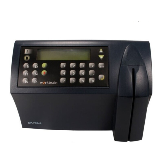
Apparatus This terminal series is enclosed in a rugged plastic molded casing and is secured to the wall using four screws and a removable panel. Biometric 32 character LCD fingerprint reader Alarm light ON button Function keys Numerical keyboard Internal reader •... -
Page 14: Front Panel
Front panel 32 character LCD with a back light display is located in the upper part of the front panel. Two arrow keys are located 32 character LCD to the right of the display panel for line up and line down maneuvering. Alarm light located to the left of the display. -
Page 15: Bottom Connection Sockets
Bottom connection sockets The bottom of the terminal contains connections sockets for all external connections. Connection cables can be inserted through the round opening in the mounting panel, or from the bottom. Information about connecting the sockets can be found on page 18. The socket openings for external connections reside at the bottom of the panel from left to right: •... -
Page 16: Internal Components
Internal components Battery back-up modules The terminal has two back-up battery modules, one for the real time clock memory and the other for operation during a power failure. The standard memory back-up module is a lithium battery, which will keep the internal clock running and the memory intact, for 30 days during a power failure. -
Page 17: Memory
The default firmware battery shutdown timeout is 15 seconds. This timeout is used unless a different timeout has been programed to the terminal using the Synel Protocol and uploaded to the terminal. During a power failure, the user presses the battery key to activate the terminal. Data can then be entered and stored in the terminal memory. -
Page 18: Unpacking
Unpacking Check the box and contents for signs of damage that may have occurred during shipment. Don’t throw away the box or any of the packing materials.Contents The terminal package contains: Phillips flat head 4x50 mm screws & anchors (3 x brick/cement 3 x plaster walls) Terminal connecting/splitter box (included only when network Detachable power cable... -
Page 19: Installation
Installation Selecting the Terminal Location (Bluetooth and Wi-FI) When selecting a place to install a terminal with wireless network communication (Bluetooth and Wi-FI) you need to consider environmental factors that effect the connection. The optimal location is where: When selecting a place to install a terminal with wireless network communication (Bluetooth and Wi- FI) you need to consider environmental factors that effect the connection. -
Page 20: Mounting The Terminal On A Wall
Mounting the terminal on a wall Make sure the unit is not plugged into a power source. If you have already connected your terminal to a PC, disconnect it. You can reconnect it after you have completed mounting the unit. The terminal contains computer components. - Page 21 Step 2:Remove the back mounting panel by sliding it to the side and pulling it out. A - Screw holes - for screwing the mounting panel in place. B - Entrance for cables wired from the wall. C -Clasps for holding cables in place. D -For cable entering terminal from below.
- Page 22 holes (A). Step 4:Drill holes using a 6 mm. (1/4”) drill bit. Live wires in the vicinity may contain 115V or 220V. Make sure not to drill into any live electric wires. Overlooking this warning may result in harmful contact with an electrical current.
-
Page 23: Communication Connections
Communication connections Step 1: Select a location for the connection box. The box must be positioned where both the communication line and the terminal can be connected to it. The terminal should be placed near the connection box, and must be within the reach of the short RJ45 cable. Step 2:Plug the communication cable from the terminal into the connection box. -
Page 24: Setting Up The Terminal (Technician Mode)
Setting up the Terminal (Technician Mode) The terminal is setup in Technician mode that is described in this chapter. To enter Technician mode you can either swipe an authorized badge or press the up/down keys simultaneously six times. Use the Enter key to scroll between screens, and the line UP/DOWN keys for moving between options within the selected screen. -
Page 25: Entering Technician Mode
Entering Technician Mode Swipe an authorized badge or press the UP/DOWN keys simultaneously 6 times. The display screen flashes and then displays the version then changes to display the TECHNICIAN MODE and the time and date alternately, (time&date are adjusted from a PC). Entering SETUP mode When you enter Technician mode you can either EXIT or SET. - Page 26 The Station (terminal) ID is the terminal’s address on a communication line. It enables multi-terminal communication. Any number from 0 to 31 may be used as the terminal ID. Again, scroll to the required Station ID number. Modem rings Choose either the number of rings or N for no rings. Network connection Programming the network connection requires addressing several sub-topics.
- Page 27 TCP/IP enables connecting multiple applications via the same address. The port number selected here is the application identification number used by the computer when communicating with the terminal. Synel applica- tions use the default port number = 3734 (a designated Synel port). However, you may change this according to your specific needs.
- Page 28 The range of the card is up to 100m. It requires installation of the relevant drivers in your PC. Set/Link Y/N: Device name: SYNEL-xxxx, you must fill-in a unique number for this terminal PIN code (Y/N): choose Y. PIN code length (1-12): PIN CODE + Length of PIN CODE PIN code: enter the pin code.
- Page 29 Network connection E = WI - FI card: The following diagram in the next maps out the flow through Technician mode setup for WIFI. After setting Authentication and Encryption you get content sensitive settings based on your previous settings. You can click the diagram nodes to jump to their explanation below.
- Page 30 Main Settings Polling Set NIC Reset Exit Enter Password Network settings Password Reset Exit Enter Password PleaseWait... Keyboard type SSID Encryption Authentication Exit no save Save & Exit TCP/IP Settings Open Input Keyboard Open SSID Save changes? My MAC - Alphanumric - Hexidecimal Shared Key My IP Address...
- Page 31 The port number selected here is the application identification number used by the computer when communicating with the terminal. Synel applications use the default port number = 3734 (a designated Synel port). However, you may change this according to your specific needs.
- Page 32 Host Port Back to WIFI diagram Synel applications use the default port number=3734. However, you may change this according to your specific needs. Use the numeric keys to change the port number. Disconct Sec Back to WIFI diagram Disconnect seconds defines the number of waiting seconds before reverting to offline mode. Click 03 to enable a fast disconnection.
- Page 33 None 64 bit (total allowed characters: in Hex 10 in Ascii 5) 128 bit (total allowed characters: Hex 26 in Ascii 13) WEP Key Specify the number of the key in the sequence of 4 keys. WEP Auth Back to WIFI diagram WEP 802.1x authorization is set by drilling down and selecting the parameters.
- Page 34 Wi Fi WEP - choose: None (Up to 26 characters) User Name User Password CCMP (Up to 26 characters) User Name User Password TKIP (Up to 26 characters) User Name User Password Reset Enter Password Back to WIFI diagram Used to change the password. Password Enter the current password.
- Page 35 Global threshold Specify the global threshold level as: '0' -Very Low, '1' - Low, '2' - Medium, '3' - High, '4' - Very High. Enrollment mode Set the enroll mode as follows: 0 – One Time - supported by all units 1 –...
-
Page 36: Resetting The Wi-Fi Card
Resetting the Wi-Fi card To restart the card: Press and hold the reset button. Disconnect the power source. Reconnect the power source. Press the reset button for 20 seconds. Note: Note: This restart process may need to be repeated more than once. When the card restarts it returns to the manufacturers default. -
Page 37: Hex Table
Hex table In the terminal HEX alphabetic values are entered using the F keys. In the following table, characters which have alphabetic values are listed with the F keys that are used to enter them in the terminal. Char HEX Char HEX Char HEX Char HEX... -
Page 38: Host Computer Interfacing
Host Computer Interfacing There are a number of different standard communication channels. The data collection terminal can be connected to the host computer using either an RS-232 or an RS-485 connection with an asynchronous serial port. RS-232 is used for a single device with a point to point connection, for distances up to 50 meters (160 ft). - Page 39 DIRECT (RS-232)/MULTI-DROP (RS-485) CONNECTION...
-
Page 40: Installing Communication Cables
Installing communication cables Follow these guidelines when installing the communications cables: The cable should not be installed near an EMI sources, such as: • Motors, generators, alternators, and transformers • Air conditioners, elevators • Radio/television transmitters, signal generators and internal communication networks Cables should not be within 30 cm. -
Page 41: Connecting Your Pc To The Sy-65
Connecting your PC to the SY-65 The SY-65 must be set to one of the RS-485 modes, i.e. 4,5,6 and 7. For more information, refer to the manual for the SY-65 communication adapter. The diagrams below describe the pin outs for the cable used to connect your PC to the SY-65 communication adapter. -
Page 42: Connecting The Sy-65 To A Connection Box
Connecting the SY-65 to a connection box A 24 gauge, shielded two wire twisted pair cable should be used to connect the SY-65 to a connection box. • Open the connection box. • Connect the -TRX wire to the connection marked OR. •... -
Page 43: Making A Multi-Drop Connection
Making a multi-drop connection Most computers use DTE type connectors on their RS-232 ports. The terminal is equipped with an RJ45 (telephone jack) connector. Therefore, you will need a connection box intermediating the terminal and the host. All terminals and their connection boxes are connected in exactly the same way, regardless of their terminal IDs. -
Page 44: Cable From The Terminal To The Connection Box
Cable from the terminal to the connection box This is a standard 6 wire telephone cable with an RJ45 connector cable which is supplied with the terminal. The pin locations are illustrated below to allow you to prepare such a cable. The length of the cable should not exceed 30 meters (98feet). -
Page 45: Terminal To Rs-232 Port Direct Connection
terminal to RS-232 port direct connection • Open the connection box. • Connect the TXD wire to the connection marked GR. • Connect the RXD wire to the connection marked YL. Connect the ground wire to the connection marked RD. RJ45... -
Page 46: Maintenance
Maintenance This section gives instructions for maintaining good working order for the terminal. The issues described are: • Physical Maintenance • Calibrating the Real Time Clock (RTC) • How to cause the memory to crash • Formatting the memory if a crash occurs •... -
Page 47: Badge Readers
Badge Readers Once a month: • Magnetic badge readers: Once a month - use a special cleaning badge made of plastic with a polishing paper (made of Al2O3, with a grain size of approximately 16 microns) attached to the part of the badge where it contacts the magnetic head. Swipe the badge once or twice. -
Page 48: Fingerprint Sensor Cleaning And Care
Fingerprint sensor cleaning and care A sensor is designed to provide years of trouble- free service. Although maintenance and handling requirements are few in number, observance of a few basic maintenance procedures help ensure a high level of performance over time. - Page 49 For Capacitive Sensors Use Isopropyl alcohol (rubbing alcohol) and a clean cotton cloth or tissue paper to remove oily deposits. Do not use a soiled cloth or tissue paper. A clean cotton cloth or tissue paper will absorb the deposits, but a soiled cloth will smear the deposits over the sensor’s surface.
- Page 50 1.3.2 Caring for the Fingerprint Sensor. • Do not place the fingerprint sensor close to a heat source, such as a radiator or hot plate. • Do not subject the fingerprint sensor to heavy shocks/vibrations. • Do not allow the sensor to come in contact with metallic objects. Conditions.
- Page 51 • Visually check the battery for leakage. Clean all of the electrical contacts inside the terminal with a contact cleaner. Checking Backup battery: Making sure that the backup battery is in good condition, according to the following steps: 1. Collect and clear all the data stored in the terminal. 2.
-
Page 52: Calibrating The Real Time Clock (Rtc)
Calibrating the Real Time Clock (RTC) This operation must be performed by qualified and authorized personnel only! When working with an open unit, make sure to unplug the unit wherever the instructions call for it. Take extreme care during the stages where the terminal is plugged into a power source. - Page 53 12. Press once on Enter, for N (no). Use line up/down to scroll when selecting the Y (yes) option. 13. Calibrate the RTC of the terminal to 3.90625 milliseconds + 0.00003 by turning the screw on the variable capacitor at C18. 14.
-
Page 54: How To Cause The Memory To Crash
How to cause the memory to crash This operation must be performed by qualified and authorized personnel only! When working with an open unit, make sure to unplug the unit wherever the instructions call for it. Take extreme care during the stages where the terminal is plugged into a power source. -
Page 55: Formatting The Memory If A Crash Occurs
Formatting the memory if a crash occurs If the memory crashes a CRASH message will appear. You will need to clear the terminal’s memory and return the terminal to the NO PROGRAMMING state according to the procedure below. 1. Press 6 times on the 0 key. An asterisk appears for each time that this key is pressed. 2. - Page 56 8. You receive a NO PROG display. The terminal then will be in the Technician mode. The message on the display will alternate between and the date and time in the following TECHNICIAN MODE format: DD/DW hh:mm:ss where DW represents the day of the week. If you make an error during steps 3 through 6, the terminal will revert to the state just prior to step 3.
- Page 57 COMPONENT SIDE (PCB NO. 770888-01-D)
- Page 58 PRINTED SIDE (PCB NO. 770888-01-D)
- Page 59 DISPLAY CARD...
- Page 60 Appendix A - External Connectors HOST RJ-45 (8 pin) Communication with Host computer Signal Value Remarks RS-485 (-TRX) Volt RS-485 (+TRX) Volt RS – 232 (TXD) Standard RS-232 levels +15Vdc RS – 232 (RXD) Standard RS-232 levels +15Vdc 7/8 NC...
- Page 61 Ser I - RJ- 11 (6 Pin) Secondary serial channel for printer, scales or external PRintX Signal Value Remarks RS-232 TxD Finger print Transmit data RS-232 Finger print/Printer busy RxDReceive data RS - 232 TXD Printer RS – 232 RXD Printer 5Volt When connecting an external PRintX there avoid connecting an internal PRintX!
- Page 62 C Bus – RJ 11 (6 Pin) (.NA) Pin Signal Value Remarks Serial Clock INT I2C Interrupt input Serial data P11 - External Reader 2(Magnetic/Bar code) RJ-45 (10 pin) Magnetic reader Pin Signal Value Remarks Data - For RS-422 signal only Led 1 Led 2 Led 3...
- Page 63 Led 3 DATA Data +, For RS – 422 Wiegand Pin Signal Value Remarks Data (6) - For RS-422 Led 1 Led 2 Led 3 DATA1 Clock+, for RS-422 DATA0 + DATA+, for RS-422 Data (-) Data (-) for RS-422 Change JP18/19 accordingly.
- Page 64 Appendix B - Internal connectors Relays + sensors Signal Description number TB1-1 Sensor 1 Input TB1-2 TB2-1 Sensor 2 Input TB2-2 TB3-1 Relay 1 Normally closed TB3-2 Relay 1 Common TB3-3 Relay 1 Normally open TB4-1 Relay 2 Normally closed TB4-2 Relay 2 Common...
- Page 65 P14-6 P14-7 P14-8 Socket - P15 Signal Description number P15-1 P15-2 -TRX1 RS-485 P15-3 +TRX1 RS-485 P15-4 RXD1 RS-232 P15-5 TXD1 RS-232 P15-6 PR-Busy Net Card Sockets Socket P3 Signal Description number P3-1 P3-2 P3-3 P3-4 Host-Tx P3-5 Com. direction (TTL) Socket P101 Signal Description...
- Page 66 P2-3 RX+/OP- P2-4 P2-5 option P2-6 P2-7 Should be mounted for POE option. option J104 - needs to be ON. Fingerprint Connector P12 (Power) Signal Description number P12-1 P12-2 Connector P13 Signal Description number P13-1 T1 Out RS-232 P13-2 P13-3 R1 Input RS-232 Connector P20 Signal...
- Page 67 P20-2 #DSR- Optional for WIFI. When using this option WIFI JP125 needs to be ON. Connector P4 Signal Description number P4-1 BAT+ Rechargeable BAT (+) P4-2 BAT- Rechargeable BAT (-) Connector PL1 Signal Description number PL1-1 Power supply PL1-2 Connector P6 (LCD) Signal Description number...
- Page 68 P6-19 ON-SWITCH P6-20...
- Page 69 Connector P9 (PSD - JTAG PORT) Signal Description number P9-1 P9-2 TRST P9-3 P9-4 CNTL P9-5 P9-6 TSTAT P9-7 P9-8 P9-9 P9-10 P9-11 P9-12 P9-13 P9-14 TERR Connector P16 (CPLD JTAG PORT) Signal Description number P16-1 P16-2 X-TDI P16-3 X-TMS P16-4 X-TDO P16-5...
- Page 70 Connector P100 (optional for Lithium Battery) Signal Description number P100-1 Lithium BAT(+) P100-2 Lithium BAT(-)
- Page 71 Appendix C - Jumpers PSD Programming No. Jumper Description Value Default/Note Jtag OPEN - Normal OPEN programming work CLOSED - Programming Miscellaneous No. Jumpe Description Value Default/Note JP12 Watch Dog in OPEN WDI Disable CLOSED CLOSED - Normal WORK JP13 1-2 Normal work Normal work 2-3 Calibration...
- Page 72 12 JP5 Tamper switch [1-2] - Enabled [2-3] - Disabled 13 JP21 Connect (R2 [1-2] - External FPU Input) to the [2-3] - Printer busy printer busy or to the external 14 JP11 CLOSED - VCC ON OPEN - VCC OFF 15 JP10 Testing current CLOSED - Normal...
- Page 73 19 JP107 SY-795/ (1-2) managing the Default OPEN Modem SY-795 graphic LCD board. (2-3) CTSB for modem 20 JP106 Rechargable for future use Default OPEN battery 21 JP108 for future use (2-3) 22 J100 Buzzer ON - enable buzzer (ON) OFF - disable buzzer 23 J101 for future use...
- Page 74 Appendix D - Biometric concepts Biometric Definitions Enrollment is the operation of scanning a fingerprint, determining the quality of the fingerprint scan, and storing a good template together with associated data in the FPU memory. The following enrollment methods are available. One time –...
- Page 75 Scanning an Image When the FPU properly reads a fingerprint, it looks for image quality and fingerprint content. When a raw image is collected from the sensor during enrollment, for verification or identification, the FPU searches for the fingerprint core. Content scores are based on the amount of unambiguous data in the region of the core.
- Page 76 resemble the raw image, but whereas a raw image is 90K bytes, the compressed template is only around 400 bytes. Fingerprint Core is the term used to describe distinguishing print characteristics usually found in the area of the print where the topography shows the tightest curvature. Although the entire fingerprint has significant data, the “core”...
- Page 77 • When using an Authentec sensor, make sure your finger is touching the sensor’s drive ring. • It is recommended that quality be 50% and content 90% at least. • Make sure you use the finger for enrolled verification • If your finger is extremely dry, touch your forehead or the side of your nose before placing it on the sensor.
- Page 78 • Not using the Ridge- Lock may cause placing the finger in an incorrect position. This figure illustrates the user neglecting the Ridge- Lock and resulting fingerprint image. Notice how the core is well below centre and the sensor is not...
- Page 79 Reasons for Low Scores Some reasons for poor sampling results are listed below: Possible Reason Correction Finger movement while sampling Instruct the user to remain still while Veriprint is sampling. Finger not positioned properly With the fingertip raised, position the finger so that the Ridge- Lock rests comfortably within the first indentation of the finger.
- Page 80 Appendix E - Setting the terminal for Using POE (Power over Ethernet) PEO (Power over Ethernet) is a standard IEEE 802.3af. The standard provides the capability to deliver both power and data over standard Ethernet cabling. The standard provides 48 volts DC over two pairs of a four-pair cable at a maximum current of 350 mA for a maximum load power of 15.4 watts, although, after counting losses, only about 13 watts are available.
-
Page 81: Using Poe
Using POE When using POE on the terminal you will need to make the following changes: CPU Board REV-D: JP104 should be shorted / P101 should have 7 PINs. Network cars type B: V2 should be compatible with POE. C6/R7/8/9/10 should be removed P2 Should be 7 PIN JP13 should be on (1-2) Net Card Type F:... - Page 82 Programming via SYncomm Introduction The SY-780A terminals can be programmed by a SAL program to meet any requirements in the field of access control. However programming via Syncomm is much easier, but has some limitations. The SYComm program is written to accept parameters that are grouped into designated tables.
- Page 83 Terminal Programming Programming Flow Chart System tables Firmware SAL Programs JAL Parameters Scheduler System (JPL) (JPR) (FTS) (SYS) Program tables Weekly Message Input Test Data tables Valid Non Valid There is an inter-dependency between the different *.jpr tables built by the SAL program which are the body of the application.
- Page 84 The correct and logical order for building a project is to begin from the bottom of the flow chart as follows: Mandatory • Input • Test • Transaction (Test + Input) • General (Transaction to Function Key) • Weekly (General to day of week) Optional •...
- Page 85 Input Enables defining up to 4 Input sources that typify a reader/sensor. Input sources are as follows: Magnetic track 1 Requires swiping of an employee card (ANSI) Magnetic track 2 Requires swiping of an employee card (ANSI) Proximity Requires placing the card upto a distance of 6-8 cm from the reader Touch memory Bar code 3/9...
- Page 86 Valid An list of IDs of authorized cards. See screen in the page below: Please note that the IDs indicated in the Employee (see “Employees” on page 86) table and the valid table must be identical! The Valid screen is used for defining and determining access levels for each employee:...
- Page 87 Step 1:Fill-in the Valid table header row: Table Header name These constitute the header (structure) of the valid table. Record The data will be filled-in on the size right. Type length Step 2:On the right fill-in all authorized employee numbers. Step 3:On the bottom the user can allocate permitted terminals to each employee.
- Page 88 Employees Here you can assign an employee list/employee to a terminal. More than one authorized employee table can be imported from an external database Unlike the Valid table, this table includes various employee details as you can learn from the table below: Employee table header (name).
- Page 89 Employee authorized list layout. Here, employees can also be added manually! A list of the terminals to which authorized employees can be assigned and thus allowed access. Additional features that can be used or disregarded: Create message table/Create scheduler table/Create total hours table- these are employee specific messages to be displayed for the eyes of that employee only! Add employee name/Assign Terminals/Security group - these fields that...
- Page 90 minal/s, or the Security Group check box to assign employees according to a security group. Step 4:If you use the Assign Terminals option, you must now add a terminal to the Permitted terminals for a specified employee. Mark one or more terminal/s on the Terminals list and use arrow to move it to the permitted terminals list.
- Page 91 Printer Notes This feature is used for printing labels (For example.: meals). First you must go to Set-up | Program Configuration | Printer and define the printer type you are using in your organization. There are several predefined default printer definitions. If none match your specific printer brand, you should define printer parameters.
- Page 92 Test This is a mini set-up table for activities and terms to be performed on the transactions. It is possible to perform one activity or a sequence of several activities. Some of the relatively simple activities are: saving transactions, employee access/other validation, displaying specific timed messages. Some of the more complex activities are: calculation activities (sum, subtract, multiply, compare etc.), variable to variable, inter-buffer activities.
- Page 93 1. The header is the test name, it is recommended that the given name will portray the purpose of the test, see above screen. A new header can be created by either clicking the New button or the key. 2. The base part is where actual definitions are set, when double clicking a row the following screen appear...
- Page 94 Step 1:Fill-in a test name and number. Step 2:The templates are comprised of different activities: Most templates are divided into 3 parts: Operation- A check to be performed, different from template to template. OK- Further to the operation how to confirm or what other activities will follow. Similar for most tem- plates.
- Page 95 plates. The OK/Fail sections screens are displayed below: Display message Enables choosing a constant message from the system messages list. Display end Enables displaying variables of input data. Relay Enables activating a relay. Buzzer alert Enables activating an alert buzzer. Buzzer OK Enables activating an OK buzzer.
- Page 96 Write transaction Transmits data that was stored to the terminal’s memory. Cannot be displayed. Go to module Enables a cyclic flow to the same transaction. The terminal reverts to the defined default function.
- Page 97 Buffers: What data will be displayed on the terminal’s prompt: N - None No check will be performed. I - Input data The last value that was received by the terminal. L - Input length The Number of designated spaces for counting total value length.
- Page 98 Below find an outline of defining Operation for templates: Length check Defines the input length limitation (KB, card number, identification ID etc.) and the offset of that input number. Check Enables comparing field variables. value...
- Page 99 Operate Enables performing various calculations between buffers. i.e.: This feature is useful when printing, for placing variables in the printer buffer: AD= summary, SU= subtract, MV= Move, AN=Pairing bytes logically, OR= alternating 2 bytes logically, XR=Exclusive XOR operator, NU=numeric check...
- Page 100 Source Enables checking: check Primary source is the input source: what reader is operated. According to this the software will apply accordingly. The reader number is a secondary source. Reader Status code is unique for each output type as follows: Readers- E= read error, D=data read OK Keypad- N=numeric or Enter key (If only Enter then IL=0)
- Page 101 Store Enables adding transaction data to a buffer. transaction Write Enables saving all transaction steps (see transaction Transaction folder) in the terminal’s memory. Later this data can be collected by the host. Transaction In this screen the user can define a multi-step transaction, combining Test, Input and prompt message definitions.
- Page 102 Define all hardware parameters: Key function- Determine function allocation to terminal keys. Display parameters- What error message will be displayed on the prompt. Also you must choose a date/time format as per the terminal you are using as follows: DD/MM MM/DD HH:mm HH:mm a/p...
- Page 103 Global parameters- Timing of terminal activities. Sensor parameters- sensor operational parameter. Error notification- Setting-up error indicators. Weekly Combines General definitions of the terminal function keys with a day of the week. Thus, the terminal can be used differently for each day.
- Page 104 Appendix G -Wiegand Algorithms The following decoding methods can be used for the terminals Wiegand interface: 32 bit Algorithm 2: Input: 1 (Even Parity bit) - 15 bits - 15 bits - 1 (Odd Parity bit) Output - Facility code 5 bytes (15 bits) Card Number 5 bytes (15 bits) Algorithm 3: Input: 1 (Even Parity bit) - 10 bits - 20 bits - 1 (Odd Parity bit)
- Page 105 33 bit Algorithm 0 Input: 1 (Even Parity bit) - 7 bits - 24 bits - 1 (Odd Parity bit) Output - Facility code 2 bytes (7 bits) Card Number 8 bytes (24 bits) Algorithm 1 Input: 1 (Even Parity bit) - 10 bits - 21 bits - 1 (Odd Parity bit) Output - Facility code 4 bytes (10 bits) Card Number 7 bytes (21 bits) Algorithm 2...
- Page 106 Synel Industries Ltd. 2 Hamada St. POB 142, Yokneam Industrial Park, Israel, 20692 Tel: +972-4-959 6777Fax: +972-4-959 0729 Site: www.synel.com Tel-Aviv BranchTel: +972 9 775 0400 UK BranchTel: +44-181-900 9991 NA BranchTel: +1-905-678 2605...
Need help?
Do you have a question about the SY-780A and is the answer not in the manual?
Questions and answers