Table of Contents
Advertisement
Quick Links
Advertisement
Table of Contents

Related Manuals for Vdwall LVP40X

Summary of Contents for Vdwall LVP40X
-
Page 1: User Manual
LVP40X LED HD Video Wall Processor User Manual SHENZHEN VDWALL CO., LTD. -
Page 2: Table Of Contents
Chapter 3 Frontal panel operations...............7 3-1 Diagram of frontal panel............7 3-2 Button instructions (operation model)........7 Chapter 4 Setup.....................11 4-1 Enter setup of LVP40X............12 4-2 Select language..............13 4-3 Output resolution setup............13 4-4 Color / definition..............14 4-5 PIP / POP output image setup..........15 4-6 Text Overlay setup..............18... -
Page 3: Chapter 1 Safety Precautions
LVP40X User Manual Chapter 1 Safety Precautions Danger! There is high voltage in the processor, to prevent any unexpected hazard, unless you are maintenance, please do not open the cover of the device. Warning! 1. This device shall not encounter water sprinkle or splash, please do not place anything containing water on this device. -
Page 4: Chapter 2 Connections Of Hardware
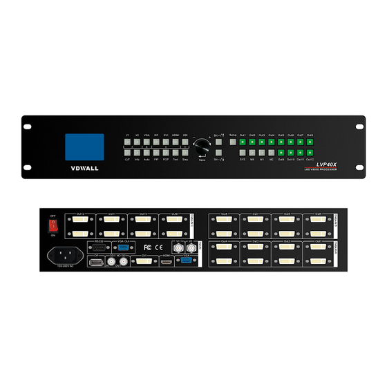
3) Obvious malpractice is found or performance degrades. Chapter 2 Connections of hardware 2-1 Rear view Figure 2-1 Rear view 2-2 Port description 1. Video Input LVP40X supports 7-channel signal input, including: Port name Description V1~V2 2-channel PAL/NTSC composite video input 1-channel computer analog signal input... - Page 5 LVP40X User Manual 2. Video Output Port name Description Each DVI out controls a piece of small LED, the image to be imported can be any part cut from the input image. LVP404: 4x2DVI OUT LVP408: 8x2DVI OUT LVP412: 12x2DVI OUT...
-
Page 6: Connection Diagram
LVP40X User Manual 2-3 Connection diagram Figure 2-2 Connection diagram www.videowall.cn... -
Page 7: Chapter 3 Frontal Panel Operations
Figure 3-1 Diagram of frontal panel 3-2 Button instructions (operation mode): There are 33 buttons and one knob on the frontal panel of LVP40X, all these buttons will be operable after start. they have the following functions as described below:... - Page 8 Increase output image brightness of LVP40X, the BRT + highest brightness is 32. LVP40X supports 8 levels of output Brightness, “0” represents the lowest brightness, and 32 represents the highest brightness. To ensure full gray level of output image, normally the output...
- Page 9 LVP40X User Manual Figure 3-2 While in operation mode, press “Out1”, the input and output parameters of current DVI Out1 will appear in LCD at the location as shown in above figure. Press “Out2”, the input and output parameters of current DVI Out2 will appear in LCD at the location as shown in above figure.
- Page 10 7) PIP / POP PIP mode of LVP40X allows user to insert a PIP window in current picture, and the size and location of the PIP window can be changed freely. The signals to be displayed in PIP window can either be signals coming from other groups or be current signal itself.
-
Page 11: Chapter 4 Setup
For ordinary users, unless they have received adequate technical training, they shouldn’t attempt to make the following settings! There are 29 items in 6 categories available for you to set in LVP40X. Technicians can set these items as necessary, for details see the table below:... -
Page 12: Enter Setup Of Lvp40X
26 Low gray bias device reset 27 White balance adjustment 4-1 Enter Setup of LVP40X Press “Setup” for consecutive 8 times while in operation mode, “Password: 8 Enter Setup …” will appear in LCD, LVP40X will enter the No.1 setup item. www.videowall.cn... -
Page 13: Select Language
4-2 Select language Item 1: “Language “ Figure 4-1 After entering setting mode, LVP40X will enter the first setting item “Language”. LVP40X supports Chinese and English display, Press “knob” to select either of them, then Press “Enter” to save and validate the setting. -
Page 14: Color / Definition
Item 3: “Color” Figure 4-3 For V1, V2, DP, HDMI and SDI video input source, LVP40X can set color saturation for them ranging from 22 to 38. The lower this value is, the weaker the color looks; the higher this value is, the stronger the color looks. -
Page 15: Pip/Pop Output Image Setup
4-5 PIP/POP Output Image Setup Items 4~7: “PIP image output setup” Figure 4-5 After LVP40X enters “PIP” mode, relevant setup information will appear in LCD in the format as shown in the figure below: Figure 4-6 As above figure shows, the LCD consists of 6 sectors, table below lists... - Page 16 New value; or ! : it means New value has been saved LVP40X PIP image window is located in LED screen. As in PIP mode the PIP image is to be zoomed-in/out after being added to background, it means that 4 values listed in items 9~12 in the table below don’t...
- Page 17 LVP40X User Manual Item 8: “PIP_Frame” Figure 4-8 User can customize frame mode in PIP image window of LVP40X. There are 4 setting options, i.e.: “No frame” , “black 2 lines” , “white 2 lines” and “blue 2 lines” .
-
Page 18: Text Overlay Setup
Item 11: “Text_Thd_RGB” Figure 4-11 LVP40X users can set R, G, B values of text threshold value by themselves, the three values can be set to be the same within 0~252. Item 12~14: “ Text_Thd_R/G/B” www.videowall.cn... -
Page 19: Device Id
LVP40X, Software in the Device ID and the same ID of LVP40X equipment, and equipment to establish a communication software side. If more than one LVP40X set different Device ID, can be achieved by a series of RS232 data line can be the implementation and control. www.videowall.cn... -
Page 20: Splicing Setup
4-8 Splicing setup LVP40X supports splicing 4 pieces of Leds of maximum 1920x1080 pixels into one big Led. A single set of LVP40X supports Led of maximum 7680x1080, 1600x4800 or 3840x2160 pixels. It supports 3 splicing modes, i.e.: Mode0, Mode1, Mode2. User can seamlessly switch between three preset modes quickly by pressing the buttons “Mode0”, “Mode1”, “Mode2”. - Page 21 Output vertical height =960 Output vertical start =0 Output vertical start =0 Then, we can setup LVP40X. As the figure below shows, to make up a large integrated picture, you should cut the corresponding parts from the input image. Input image (0,0)...
- Page 22 LVP40X User Manual Item No. 16: “Input horizontal width “ Figure 4-15 After LVP40X enters “Splicing Setup” mode, relevant setup information will appear in LCD display in the format as shown in figure below: Figure 4-16 As above figure shows, the LCD consists of 8 sectors, table below lists...
- Page 23 LVP40X User Manual to select “New value” , when the value you desire appears, Press “ Enter” to save the setting, Press “Step” to select “Step value for number setup” . While in any setup mode, Press “ Out1” , “ Out2” , “ Out3”...
- Page 24 LVP40X User Manual Press “Out2” to select DVI output port for current setup=Out2, set Input horizontal start =960; Press “Out3” to select DVI output port for current setup=Out3, set Input horizontal start =0; Press “Out4” to select DVI output port for current setup=Out4, set Input horizontal start =960;...
- Page 25 LVP40X User Manual Item No. 19: “Input vertical start” Figure 4-19 In this item, user can Press “Mode0” “Mode1” “Mode2” to select “Save mode of current setup”; Press “ Out1” “Out2” “Out3” “Out4” to select “DVI output port for current setup”; Press “knob” to select “New value” , when the value you desire appears, Press “Enter”...
- Page 26 LVP40X User Manual In this item, user can Press “Mode0” “Mode1” “Mode2” to select “Save mode of current setup”; Press “Out1” “Out2” “Out3” “Out4” to select “DVI output port for current setup” ; Press “knob” to select “New value” , when the value you desire appears, Press “Enter”...
- Page 27 LVP40X User Manual Press “ Out1” to select DVI output port for current setup=Out1, set Output horizontal start =0; Press “ Out2” to select DVI output port for current setup=Out2, set Output horizontal start =0; Press “ Out3” to select DVI output port for current setup=Out3, set Output horizontal start =0;...
- Page 28 LVP40X User Manual Item No. 23: “Output vertical start” Figure 4-23 In this item, user can Press “Mode0” “Mode1” “Mode2” to select “Save mode of current setup”; Press “Out1” “Out2” “Out3” “Out4” to select “DVI output port for current setup” ; Press“knob” to select “New value” , when the value you desire appears, Press“Enter”...
-
Page 29: Exit Setup
LVP40X User Manual 4-9 Exit setup Item 24: “Exit Setup “ Figure 4-24 Press “↑” to move to the last item: “Exit setup” , then press “knob” to select “YES” , then press “Enter” to exit setup mode. If you press “Setup” key while in any setup mode, the system will skip to the No.27 item. - Page 30 LVP40X User Manual Figure 4-26 Click “knob” to select “Yes”, then click “Enter” to reset the factory settings, the moment the system will remind you “The device is resetting, please restart the machine”, just follow the instruction. Item 27: “White Balance Adjustment”...
-
Page 31: Chapter 5 Specifications
LVP40X User Manual Chapter 5 Specifications Inputs 2×Composite video 1×DP(DisplayPort) 1×VGA (RGBHV) Number/Type 1×DVI 1×HDMI 1×SDI (HDSDI) Video system PAL/NTSC Composite Video 1V (p_p) / 75Ω Scope/Impedance VGA Format PC (VESA) ≤1600x1200 @60HZ VGA Scope/Impedance R, G, B = 0.7 V (p_p) / 75Ω... - Page 32 Others Control Panel Button,RS232 Power 100-240VAC 60W 50/60Hz 5-40 ℃ Operating Temp Humidity 15-85% 190 mm (height) ×400mm (width) ×525mm Dimensions (length) Weight 3.8Kg Net Weight: Gross Weight: 6.2Kg Note: LVP40X includes the following 3 models: LVP404 LVP408 LVP412 www.videowall.cn...
Need help?
Do you have a question about the LVP40X and is the answer not in the manual?
Questions and answers