Table of Contents
Advertisement
Quick Links
Up
Pocket
Start
Quick Instructions
for initial start-up of
WARNING:This is a brief guide only. It does not give safety
information. Incorrect installation or operation of the drive
!
could cause personal injury or equipment damage. Refer to
Unidrive 6 User Guide for essential safety information.
http://nicontrols.com
1
Advertisement
Table of Contents

Subscribe to Our Youtube Channel
Summary of Contents for Control Technologies unidrive sp
- Page 1 Pocket Start Quick Instructions for initial start-up of WARNING:This is a brief guide only. It does not give safety information. Incorrect installation or operation of the drive could cause personal injury or equipment damage. Refer to Unidrive 6 User Guide for essential safety information. http://nicontrols.com...
- Page 2 N O R T H E R N INDUSTRIAL W W W . N I C O N T R O L S . C O M ESTABLISHED IN 1978 Northern Industrial Thwaites Close Blackburn Lancashire BB1 2QQ United Kingdom Cert No.
-
Page 3: Power Wiring
Power Wiring DC Connections *Thermal *Thermal overload overload Braking Braking protection protection Resistor Resistor device device (Size 1 only) (Sizes 2 & 3) -DC +DC DC1 DC2 Sizes 2 and 3 Size 1 Internal EMC filter WARNING For complete wiring and fusing instructions, refer to the Unidrive 6 User Guide Thermal overload for... -
Page 4: Control Wiring
Control Wiring Wire the Unidrive 6 control circuits in accordance with drawing below. Terminal Strips Default Terminal Functions Polarised signal connectors 41 42 0 V Common 0 V Common 24 V dc external supply input 24 V dc 0 V Common +10 V dc Dig. -
Page 5: Encoder Wiring
Encoder Wiring Closed Loop Vector Encoder connector 15 way D-type U V W as standard on Unidrive 6 Terminal Connections Terminal Connections Servo Encoder connector for Unimotor U V W 15 way D-type as standard on Unidrive 6 Terminal Connections •... -
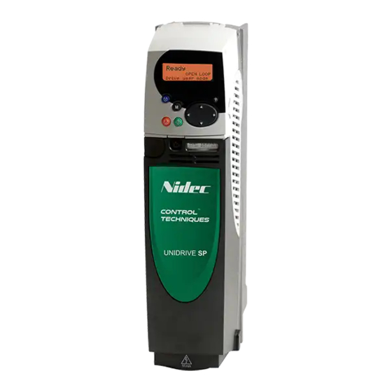
Page 6: Keypad And Display
Keypad & Display Lower Display Upper Display Parameter value Parameter number or trip code or drive status Mode (black) button Control buttons changes between Fwd/Rev (blue) button parameter edit and Stop/Reset (red) button monitor mode Start (green) button Joypad Used to select a parameter and change its value Display Modes Reset to Factory Defaults... -
Page 7: Open Loop Start-Up
Open Loop Start-up The Unidrive 6 default operating mode is Open Loop. See Control Wiring diagram for default connections. Before power-up Ensure: • The drive enable signal is not given (terminal 31) • Run signal is not given (terminal 26) •... - Page 8 Open Loop Start-up continued Autotune Unidrive 6 is able to perform either a stationary or a rotating autotune.The motor must be at a standstill before an autotune is enabled. A rotating autotune should be used whenever possible. WARNING: A rotating autotune will cause the motor to accelerate up to 2/3 base speed in the direction selected regardless of the reference provided.
-
Page 9: Closed Loop Start-Up
Closed Loop Start-up See Control Wiring section for default connections. Step Description Actions Display 0.00 Allow drive Go to Parameter 0.00 Upper = operating 1253 Enter 1253 EUR Lower = mode to be Enter 1254 USA changed Finish Step 0.48 Select Closed Go to Parameter 0.48 Upper = Loop Vector Select CL.VECt... -
Page 10: Closed Loop
Closed Loop Start-up continued Set acceleration/deceleration rates • Acceleration rate in Pr 0.03 (s/1000rpm) • Deceleration rate in Pr 0.04 (s/1000rpm) (If braking resistor fitted, set Pr 0.15 = FAST.) Autotune Unidrive 6 is able to perform either a stationary or a rotating autotune.The motor must be at a standstill before an autotune is enabled. - Page 11 Servo Start-up See Control Wiring section for default connections. Step Description Actions Display 0.00 Allow drive Go to Parameter 0.00 Upper = operating 1253 Enter 1253 EUR Lower = mode to be Enter 1254 USA changed Finish Step 0.48 Select Servo Go to Parameter 0.48 Upper = Operation Select SErVO...
- Page 12 Servo Start-up continued Set acceleration/deceleration rates • Acceleration rate in Pr 0.03 (s/1000rpm) • Deceleration rate in Pr 0.04 (s/1000rpm) (If braking resistor fitted, set Pr 0.15 = FAST.) Autotune The load must be removed from the shaft before an Autotune is performed.
-
Page 13: Display Messages
Display Messages Status Messages Upper Display Description Auto tune Autotune in progress. The autotune procedure has been initialised. ‘Auto’ and ‘tunE’ will flash alternatively on the display. Decelerating.The drive is decelerating the motor. Inhibit.The drive is inhibited and cannot be run. The drive enable signal is not applied to terminal 31 or Pr 6.15 is set to 0. -
Page 14: Basic Parameters (Menu 0)
Basic Parameters (Menu 0) http://nicontrols.com... - Page 15 Basic Parameters (Menu 0) cont. Programs all drive Drive reads all parameters from parameters to the the SMARTCARD SMARTCARD Pr 0.30 = rEAD + Pr 0.30 = Prog + Drive boots from the Boot SMARTCARD on Drive automatically power up and writes to the automatically writes SMARTCARD...
Need help?
Do you have a question about the unidrive sp and is the answer not in the manual?
Questions and answers