Table of Contents
Advertisement
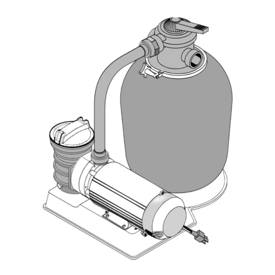
HIGH RATE SAND FILTER SYSTEM
3/4 HP
1 HP
1 HP (2-Speed)
1-1/2 HP
Sta-Rite Pool/Spa Group
Pentair Pool Products, Inc.
293 Wright Street, Delavan, WI 53115
1620 Hawkins Ave.
International: 262-728-5551, FAX: 262-728-7550
Sanford, NC 27330
www.starite.com
Tel 919-774-4151 • Fax 919-774-4841
Union City, TN • Delavan, WI • Mississauga, ON
© 2006, Sta-Rite Industries
WATERFORD SYSTEMS
For Above Ground Swimming Pools
O
W
N
E
R '
INSTALLATION, OPERATION & PARTS
15" Tank
JSAL15D
JSAL15E
S
M
A
N
U
839 0494
Models
18" Tank
JSAL180D
JSAL180E
JSAL180E
JSAL180F
This manual should be furnished to the end user
of this system; its use will reduce service calls and
chance of injury and will lengthen system life.
A
L
21" Tank
JSAL210D
JSAL210E
JSAL210E
JSAL210F
S260 (Rev. B 6/28/06)
S260 (Rev. 4/26/06)
Advertisement
Table of Contents

Related Manuals for Waterford JSAL210F

Summary of Contents for Waterford JSAL210F
- Page 1 WATERFORD SYSTEMS HIGH RATE SAND FILTER SYSTEM For Above Ground Swimming Pools R ’ 839 0494 INSTALLATION, OPERATION & PARTS Models 15" Tank 18" Tank 21" Tank 3/4 HP JSAL15D JSAL180D JSAL210D 1 HP JSAL15E JSAL180E JSAL210E 1 HP (2-Speed)
-
Page 2: Table Of Contents
HIGH-RATE SAND FILTER SYSTEM To avoid unneeded service calls, prevent possible injuries, and get the most out of your filter, READ THIS MANUAL CAREFULLY! The High Rate Sand Filter System: • Is designed to circulate and filter water in above ground swimming pools. •... -
Page 3: Safety Instructions
READ AND FOLLOW SAFETY INSTRUCTIONS! perform all pressure tests. This is the safety-alert symbol. When you see 1. Do not connect system to a high pressure or city this symbol on your valve or in this manual, look for one of the following signal words and be alert to water system. -
Page 4: Specifications/Dimensional Data
TABLE I - OUTLINE DIMENSIONS IN INCHES (mm) Filter Model 15”(406mm) Filters 24 (610) 30-7/8 (784) 15-3/4 (400) 21-11/16 (551) 26-1/16 (662) 18”(457mm) Filters 26-9/16 (675) 33-5/16 (846) 17-3/4 (451) 24-1/4 (616) 27-1/16 (692) 21” (508mm) Filters 28-11/16 (729) 34-7/16 (875) 20-3/4 (527) 26-3/8 (670) 28-9/16 (725) -
Page 5: General Information
GENERAL INFORMATION Piping: • Use teflon tape or Plasto-Joint Stik on all male con- • Clean a new pool as well as possible before filling nections of plastic pipe and fittings except unions. DO pool and operating filter. Excess dirt and large particles NOT use pipe compounds on plastic pipe;... -
Page 6: Filter Setup
Filter Setup “PUMP” should point toward pump. 4. Tighten clamp knob until clamp ends (under bolt) are Assembly: See Figures 2 through 5 for filter assembly. 1/4" (6mm) apart. Tap around outside of clamp with a mallet to help seat clamp. Loading Sand Media Hazardous pressure. -
Page 7: Electrical
Port labeled • Do not use an extension or drop cord with this system; .WATERFORD, WI. "PUMP" should 53185 it could cause a fire hazard or low voltage problems. -
Page 8: Startup/Operation/Backwash
Startup/Operation Table III–Recommended Fusing Data, 115 Volt 60 Hz Motors. (See Figure 9) Branch Hazardous suction. Can trap and tear hair Pump Motor Full Load Circuit Breaker or body parts and can cause drowning. Do not block Model No. H.P. Amps Rating (Amps) pump suction. -
Page 9: Maintenance
MAINTENANCE Hazardous pressure. To avoid explosion and possible severe or fatal injury, filter system pressure General: must not exceed 50 PSI (345 kPa) under any circum- • Wash outside of filter with a mild detergent and water. stances. NEVER test this filter system with compressed Rinse off with hose. -
Page 10: Storage/Winterizing
STORAGE/ Drain Fitting Installation/Removal WINTERIZING NOTICE: If pool is above height of filter, first close valves in pump suction and return lines to prevent drain- Pool chemicals may give off corrosive ing pool. If there are no shutoff valves installed, discon- fumes. -
Page 11: Multi-Port Valve Service
NOTICE: If Multi-Port valve is below pool water level, close suction and discharge valves before disassembly to prevent draining pool. Aquatools .WATERFORD, WI. 53185 Handle Replacement: 1. Stop pump. 2. Place handle in ‘FILTER’ position. 3. Remove pin (Key 1, Figure 13) to disconnect handle. If it cannot be removed by hand, use a hammer and cen- ter punch and lightly tap it out. - Page 12 3.Press stationary half of seal into seal plate (Key No. 9) To avoid dangerous or fatal electrical shock haz- using finger pressure only (see Figure 17). Make sure ard, turn OFF power to motor before working on seal is firmly and evenly seated. pump or motor.
-
Page 13: Troubleshooting Guide
TROUBLESHOOTING TROUBLESHOOTING GUIDE – PUMP GUIDE – FILTER Read and understand safety and operating instruc- A. Short Cycle between backwashes: tions in this manual before doing any work on NOTICE: Time between backwashes will vary with each pump. installation and between different areas of the country. A. - Page 14 Clamp Decal, Warning 32165-4030 32165-4030 32165-4030 • Information Decal 32155-4112 32155-4112 32155-4112 • Not illustrated. *See Page 15. **See Page 16. *** Models JSAL15D-59, JSAL180F-05, and JSAL210F-05 do not include 6’ hose. + Model JSALS15E uses an “ABG” series pump.
-
Page 15: Repair Parts List
REPAIR PARTS LIST POOL PUMPS 3/4 thru 1-1/2 HP Single Speed 1 Hp Dual Speed NOTICE: AT23 series models use the same front plate and seal plate as other models; however, they are rotated 90° counter-clockwise when installed. Part Description Qty. - Page 16 JWPA PUMPS CORD AND PLUG PART NUMBERS -2A2 Models -2A1 Models 2A, -A2U Models -2A4U Models Cord Ass’y with Cord Ass’y with Cord Ass’y with Twist-lock Plug Straight Plug Straight Plug 31953-0101 U117-1117 – 31953-0101 U117-1117 – 1-1/2 31953-0101 U117-1118 31953-0116 381 1293 REPAIR PARTS LIST...
- Page 17 ABG PUMPS 3345 1198 Parts are common to all models listed except as noted: Key Nos. 1, Motor; 6, Impeller; and 15 Cord are listed below. Motor No. Impeller No. Cord No. Model No. Key No. 1 Key No. 6 Key No.
- Page 18 REPAIR PARTS LIST WC112-148A MULTIPORT VALVE Aquatools .WATERFORD, WI. 53185 Part Description Qty. Number Decal, Valve Handle 32145-4016 Handle 14962-0032 Dowel Pin 35857-0021 Washer 14965-0007 Decal, Operating Instructions 14965-0020 Screw 37067-0714 Valve Cover 14965-0011 O-Ring 35505-1228 Washer 14965-0007 Washer 14965-0007...
-
Page 20: Warranty
STA-RITE LIMITED WARRANTY Pumps, filters, skimmers, underwater lights (excluding bulbs), ac- Product Specific Warranties (from date of installation) cessories and fittings manufactured by Sta-Rite are warranted to be free of defects in material and/or workmanship for one (1) year Product Limited from the original date of installation.
Need help?
Do you have a question about the JSAL210F and is the answer not in the manual?
Questions and answers