Table of Contents
Advertisement
Quick Links
ROUTER
TABLE
610 x 360MM
INSTRUCTION MANUAL
SPECIFICATIONS
Power:
230-240V~ 50Hz 10A
Table Size:
610 x 360mm
Table Height:
310mm
Fence Length:
610mm
Ø32mm (1-1/4")
Ø47mm (1-7/8")
Ø55mm (2-1/8")
ozito.com.au
WHAT'S IN THE BOX
Router Table
Mitre Gauge & Table
Inserts x 3
Switch & Guard
Starting Pin, Lock
Knobs, Bolts & Washers
Router Plate & Hex Key
RTB-001
Advertisement
Table of Contents

Summary of Contents for Ozito RTB-001
- Page 1 Power: 230-240V~ 50Hz 10A Table Size: 610 x 360mm Table Height: 310mm Fence Length: 610mm Switch & Guard Table Inserts: Ø32mm (1-1/4”) Ø47mm (1-7/8”) Ø55mm (2-1/8”) ozito.com.au Starting Pin, Lock Knobs, Bolts & Washers Router Plate & Hex Key RTB-001...
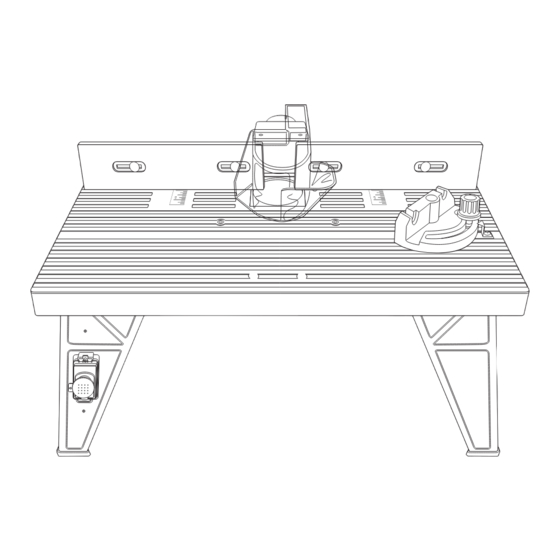
- Page 2 KNOW YOUR PRODUCT SETUP & PREPARATION ROUTER TABLE 1. ASSEMBLY 1 Outfeed Fence 6 Table The router table must be fully assembled before use. 2 On/Off Switch 7 Infeed Fence 3 Switch Leg 8 Mitre Gauge Attaching the legs. 4 Guard 9 Mitre Gauge Lock Knob 1.
- Page 3 The router plate supplied has table insert to secure it in the screw holes to suit Ozito ROU- depression. 5000 & ROU-7100 routers. If the screw holes in the router plate don’t match the mounting...
- Page 4 Use The material must be fed against the appropriate fasteners and bolts to cutting edge of the router bit, ensure secure the router table to the work that the workpiece is tight against the bench. fence. RTB-001...
- Page 5 SPARE PARTS THINNER, OR SIMILAR HIGHLY VOLATILE SOLVENTS TO CLEAN THE ROUTER TABLE. Note: Ozito Industries will not be responsible for any damage or injuries caused by the repair of the drill by an unauthorised person or by mishandling Switch Box SPRTB001-29 of the drill.
- Page 6 Tool: SPARE PARTS Model No. The following is a list of spare parts carried by Ozito. Please contact Customer Service for any parts not listed. Item Item Description Part No. Description Part No. Switch Box SPRTB001-29 Tightening Knob SPRTB001-13 Tensioning Knob...
- Page 7 Note: The supply of 230V and 240V on Ozito tools are interchangeable for Australia and New Zealand. If the supply cord is damaged, it must be replaced by an electrician or a power tool repairer in order to avoid a hazard.
- Page 8 • Failure to perform maintenance as set out within the instruction manual. • If the tool is disassembled or tampered with in any way. • Professional, industrial or high frequency use. OZITO Australia/New Zealand (Head Office) 1-23 Letcon Drive, Bangholme, Victoria, Australia 3175. 1013...
Need help?
Do you have a question about the RTB-001 and is the answer not in the manual?
Questions and answers