
Related Manuals for Samyung STR-6000A

Summary of Contents for Samyung STR-6000A
- Page 1 MARINE DSC VHF RADIO TELEPHONE FOR GMDSS OPERATING MANUAL STR- 6000A SAMYUNGENC CO.,LTD.
- Page 2 When Distress Call is received, it is necessary to inform a person on duty about this. 2. How to make the initial set-up in installation For the below items, the initial set-up should be made in installation before its actual operation. Please contact SAMYUNG ENC or any agent dealers for the information.
- Page 3 2-1 How to check out power supply Input voltage in VHF main unit: Confirm that DC13.6V is supplied. 2-2 How to transmit and receive DSC In order to use DSC function, make sure that any MMSI number available must be input first.
-
Page 4: Table Of Contents
............................10 3.1. STR-6000A Standards..............10 3.2. Transmitting Unit ................10 3.3. Receiving Unit ................11 3.4. Dedicated Receiving Unit ............... 11 Chapter 4. How to Operation Chapter 4. How to Operation ........ Chapter 4. How to Operation Chapter 4. - Page 5 4.4.3.4. LCD BACKLIGHT ............26 4.4.3.5. LCD CONTRAST ............26 4.4.3.6. GPS FUNCTION SET ............. 26 4.4.3.7. MANUAL GPS/TIME............27 4.4.3.8. DSC SET ..............27 4.4.3.9. RADIO SET ..............28 4.4.3.10. REAL TIME CLOCK(Current time change)......28 4.4.3.11. FACTORY RESET(MENU SETUP INITIALIZATION) ..... 28 4.4.3.12.
- Page 6 5.2. Selection of Installation Position for Main Units of STR-6000A .... 50 5.3. Installation for main unit of STR-6000A..........50 5.4. Cabling ..................52 5.4.1. Power Connection ..............53 5.4.2. Connects to External Speaker ..........53 5.4.3. How to setup Antenna ............53 5.4.4.
-
Page 7: Chapter 1. Introduction
Chapter 1. Introduction 1.1. Introduction STR-6000A includes DSC/VHF radio telephone and DSC receiver required by the Global Maritime Distress and Safety System(GMDSS) and is designed to be compact and lightweight for easy installation in any vessels engaged in international voyages and near-going vessels. - Page 8 Such functions as TAG CHANNEL SCANNING, ALL CHANNEL SCANNING, GROUP-CHANNEL SCANNING and DUAL WATCH allow user to listen to any specific channel. Besides the existing voice communications, it is available to work on communications for distress, urgency, safety and other routines as well by using DSC function. In case that the coast station is working on automatic connection service of public communications network, it is available to auto-connect the general telephone through the designation of the telephone number on the equipment.
-
Page 9: Chapter 2. Configuration
Chapter 2. Configuration The equipment consists of as follows; 2.1. Standards Name Model Quantity Remarks VHF Radio Main Unit STR-6000A 1 Set Including HAND MIC Manual STR-6000A-ME 1 Lot M02-0031-00 2.2. Option Name Model Remarks Including SAN-150 (RX/TX) 3dBi CABLE/BRACKET... -
Page 10: Chapter 3. Specifications
Chapter 3. Specifications 3.1. STR-6000A Standards TX Frequency 156.025MHz ~ 157.425MHz RX Frequency 156.050MHz ~ 163.275MHz ITU Channel: 55 Number of Channels USA Channel: 53 CANADA Channel: 60 WEATHER Channel: 10 Radio Wave Mode FM(16K0G3E), DSC(16K0G2B) Channel Interval 25kHz Communication Mode... -
Page 11: Receiving Unit
3.3. Receiving Unit Receive System Double Conversation Super Heterodyne 1st 21.7MHz Intermediate Frequencies 2nd 450kHz Local Oscillation Frequency Receiving Frequency - 21.7MHz Local Oscillation Mode SYNTHESIZER Mode 0.32uV (20dB SINAD) Sensitivity 0.22uV (12dB SINAD) Audio Frequency Response -6dB/octave Squelch Sensitivity 0.22uV Co-Channel Rejection -10dB ~ 0dB... -
Page 12: Chapter 4. How To Operation
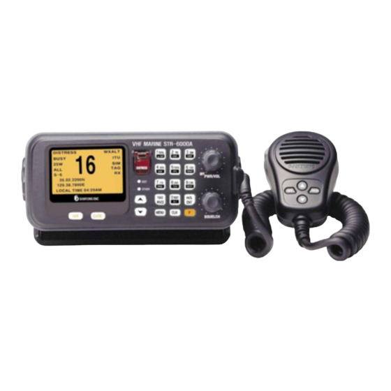
Chapter 4. How to Operation 4.1. Unit Description 4.1.1. Front Panel ① LCD Front Display Screen. Transmit distress call (Alert) MESSAGE. (※ You MUST NOT make a test of the transmission !! ) ② Push and hold down for 3 seconds, then the distress call will be activated. - Page 13 Short time press is for DSC Calling and long time press is for ⑧ MENU function. ⑨ This is ‘ESCAPE’ function in MENU mode. ⑩ It means this is being used as FUNCTION button. ⑪ PWR/VOL (Power Knob) Power ON/OFF and Volume Control. ⑫...
- Page 14 ⑬ Button description Input “1” when selects CH and inputs digit. When used this button, it works ON/OFF for dual watch function. (It receives the message by switching over between the existing CH and CH16 each other continuously.) When inputs character, convert from 1→ space → Q →to Z in order and ENT.
- Page 15 When selects CH and inputs digit, input “6”. When used this button, it can set up TAG at selected CH. When inputs character, convert from 6 → M → N → to O in order and When selects CH and inputs digit, input “7”. When used this button, it can set up to ITU MODE..
-
Page 16: Microphone
4.1.2. Microphone ① PTT : If pressed, it goes to transmission. ② MIC : Condenser Mic ③ Key Pad : : To convert to the current CH and CH16. : It is used as Enter button for setting-up input data in MENU mode, while at normal times it is used for switching-over Tx power between 25W and 1W. - Page 17 Handmic Handmic Box...
-
Page 18: Lcd Screen Description
4.2. LCD Screen Description Item Function Description DISTRESS CH Name BUSY It represents detecting the sensitivity signal in existing CH.. 25W(01W) It represents Tx Power. It represents the kinds of SCAN. It plays multi-scan between the existing CH and CH16. (It will be converted when scanning.) It indicates own ship’s latitude. -
Page 19: Vhf Operation
4.3. VHF Operation 4.3.1. Channel Selection 4.3.1.1. Channel 16 CH.16 is for distress and safety, and it should be monitored through dual-watch and tri-watch. Whenever selected key, it shifted from the current CH → CH 16 → CH 9 → current CH. -
Page 20: Weather Channel
4.3.2. Weather Channel It can receive 10 numbers of weather channel provided by NOAA (National Oceanographic and Atmospheric Administration). STR-6000A can detect the alert sound of selected weather channel from the regular channel or the one during the channel scanning When selected it converts between weather channel and general channel. - Page 21 (STR-6000A Main Body) (STR-6000A Microphone)
-
Page 22: Menu Setup And Construction
4.4. Menu Setup and Construction 4.4.1. Menu Construction 1. FRIENDS MMSI LIST 2. GROUP MMSI LIST 3. TELEPHONE LIST 4. LCD BACKLIGHT 5. LCD CONTRAST GPS TIME OFFSET TIME DISPLAY FORMAT TIME DISPLAY ON/OFF 6. GPS FUNCTION SET LL DISPLAY ON/OFF GPS ALERT ON/OFF 7. - Page 23 Menu Select 1. DISTRESS CALL 2. ALL SHIP CALL Press MENU 3. INDIVIDUAL CALL button shortly 4. AUTO/SEMI CALL -- CALL ITEM SELECT-- 5. TEST CALL 6. GROUP CALL 7. POSITION POLL 8. DISTRESS RELAY 9. DISTRESS RLY ACK 10. DISTRESS ACK 11.
-
Page 24: Menu Screen Construction And Initialization
4.4.2. Menu Screen Construction and Initialization Press button over one (1) second to get into the various Menu. 1. FRIENDS MMSI LIST ADD NEW FRIEND Friend ID register 2. GROUP MMSI LIST ADD NEW GROUP Group ID register 3. TELEPHONE LIST ADD NEW TELEPHONE Call ID register 4. -
Page 25: Menu Setup
4.4.3. Menu Setup Press button at greater length. Overall construction of MENU Screen is as follows. Item Selection : From above screen, shift the cursor by using button and press button to select the current item. 4.4.3.1. FRIENDS MMSI LIST It can add/edit/delete the preferred friend’s name and associated MMSI up to 20 numbers. -
Page 26: Telephone List
4.4.3.3. TELEPHONE LIST It can add/edit/delete the preferred Telephone name and associated MMSI up to 10 numbers. (It can save maximum 10 numbers) To add name to TELEPHONE To edit TELEPHONE To delete TELEPHONE 4.4.3.4. LCD BACKLIGHT Set-up backlight level to adjust the brightness of LCD and Key Pad. 4.4.3.5. -
Page 27: Manual Gps/Time
4.4.3.7. MANUAL GPS/TIME LAT/LONG MANUAL SET(Input position manually) : Ship’s position and longitude is displayed on screen together with time. To display “MANUAL SETUP”, value of latitude, longitude and time will be displayed in reverse status. This display mode will be cancelled as soon as GPS receiver is connected and come to display normal mode. -
Page 28: Radio Set
DSC FUNCTION DISABLE Set Up DSC function use. MEDI/SHIP_AIRCRAFT ON/OFF MEDIcal Transponder & SHIP and AIRCRAFT use. 4.4.3.9. RADIO SET CHANNEL NAME (CH NAME) Channel name modification and deletion. CHANNEL ON/OFF(CH ON/OFF) It is used for either permitting or stopping the use of current CH. WEATHER ALERT(Weather Alarm Setup) NOAA provides with a variety weather information regarding USA or CAN channel. -
Page 29: Print Setup(Print Setup)
3 seconds in order to check button condition. PLL TEST (Test PLL condition on Tx and Rx) : It will be tested from minimum frequency to the maximum by 25KHz step. DISPLAY DEVIATION : LCD test (Display the character). SOUND TEST : Test on Bell, Emergency, Error and Alarm. SUB CPU Version : SUB CPU version check. - Page 30 navigational equipment, the data on time and position will be automatically input. It is available to manually input the time when the position data and position are decided. If the transmission is made when it is not connected with any navigational equipment or under the conditions where any single manual input has not been made, it will transmit zero information.
-
Page 31: Configuration Of Call Screen
4.5.1. Configuration of CALL Screen Press button in short. The whole display configuration of DSC CALL MENU is as follows; Item selection : Use buttons in the above Screen and move to the wanted item and press button. 4.5.2. CALL Menu Description and Instruction 1. -
Page 32: Distress Call(Distress Message Setup And Call)
4.5.2.1. DISTRESS CALL(Distress message SETUP and Call) On screen of CALL ITEM SELECT, select 1.DISTRESS CALL by using buttons and then press button. In order to select types of distress (Nature of Distress), select > NATURE : UNDEFINE list and then press button. - Page 33 In order to input distress position (POSITION), select >LAT / > LONG list by using buttons and then press button. It makes cursor blink and then input wanted longitude/latitude on the blinking cursor. After select TIME-UTC buttons and then press button.
-
Page 34: All Ships Message Setup And Call
4.5.2.2. ALL SHIPS MESSAGE SETUP AND CALL Select 2.ALL SHIP CALL list on CALL ITEM SELECT screen by using buttons and then press button. ‘CATEGORY' list is a function for selecting SAFETY or URGENCY, either and press button after move the cursor to > CATEGORY list by using buttons. -
Page 35: Individual Message Setup And Call
After going through the edition of MESSAGE, select > TRANSMIT DSC list and transmit by suing buttons. 4.5.2.3. INDIVIDUAL MESSAGE SETUP AND CALL Press button after select 3. INDIVIDUAL CALL list on CALL ITEM SELECT screen by using buttons. It makes following screens. Press button after select >... - Page 36 By using button, select and press > CATEGORY button then following small screen shown up. Here on the item where the cursor is flickering, by using button and press button. By using button, select > TELECMD1 and press button then following small screen comes up and again press button.
-
Page 37: Auto/Semi-Auto Message Edit And Call
button to send out message one time. 4.5.2.4. AUTO/SEMI-AUTO Message Edit and Call This function as an option will be further realized soon. 4.5.2.5. TEST CALL This function is used for testing call, following procedure in editing and calling for position messages shall be done. On CALL ITEM SELECT screen, by using button, select 5. -
Page 38: Group Messsage Edit And Call
After finishing the edition of MESSAGE, press key at > TRANSMIT DSC then MESSAGE will be transmitted one time. 4.5.2.6. GROUP MESSSAGE EDIT AND CALL On CALL ITEM SELECT screen, select the item 6. GROUP CALL by using button, and press button. -
Page 39: Position Message Edit And Call
Note : Currently using CH such as CH70, CH75, CH76 shall not be set-up. After finishing message edit, select > TRANSMIT DSC item by using button and send out the message. 4.5.2.7. POSITION MESSAGE EDIT AND CALL On CALL ITEM SELECT screen, select item 7. POSITION CALL by using button and press button. -
Page 40: Distress Call Relay
After finishing the message edit, select the item > TRANSMIT DSC by using button and send-out message. 4.5.2.8. DISTRESS CALL RELAY Select item8. DISTRESS RELAY on CALL ITEM SELECT screen by using button and press button. After select > FORMAT using button and press button then following small screen comes up. - Page 41 Select > ADDRESS(MMSI) using button and press button then following screen comes up. From this screen, select the appropriate item by using button and press button. Select > TRANSMIT DSC by using button and press button then following screen comes up. From this screen, select YES or NO for sending Message by using button and press button.
-
Page 42: Distress Relay Acknowledgement
4.5.2.9. DISTRESS RELAY ACKNOWLEDGEMENT On “CALL ITEM SELECT” screen, select 9. DISTRESS RLY ACK by using button and press button. It is impossible to edit Message but only possible to response at >TRANSMIT DSC after editing using button. Acknowledgement to DISTRESS in Individual Call is only one time available within 5 minutes. -
Page 43: Response To The Other Call
4.5.2.11. RESPONSE to THE OTHER CALL On “CALL ITEM SELECT” screen, Select 11. OTHERS ACK using button and press button. Select > CATEGORY from the screen by using button and press button to come up small screen where to select the item and press button. -
Page 44: Direct Relay
Select > WORK/LAT/LONG/TIME-UTC from screen respectively by using button and input the information. After finishing all information, select > TRANSMIT DSC at the following screen by using button and press button to decide YES or NO for sending Message and press button. - Page 45 Select > ADDRESS from screen using button and press button. Afterwards select the methods of input for ADDRESS (MMSI) from small screen and press button. Select > DIST-ID from screen by using button and press button. Afterwards select the methods of input for ADDRESS (MMSI) from small screen and press button.
- Page 46 Select respectively from screen using > LAT/LONG/DIST-UTC button and press button and input appropriate information. After finishing edit, select >TRANSMIT DSC using button and press button to decide YES or NO to send message and press button.
-
Page 47: Recveiving Distress Read
4.5.2.13. RECVEIVING DISTRESS READ On “CALL ITEM SELECT” screen, select 13. RCV DISTRESS READ using button and press button. Then following message related to receiving distress is seen.. Display RCV DISTRESS READ screen as follows ; RCV : 08 : means for 8 received messages. PRE : 1 : Display a message from 7 to 1 if press button. -
Page 48: Dsc Message Receiving
4.5.2.15. DSC Message Receiving Display a message which is just received with alarm. Stop a alarm if press button and go back to main screen. Press button over twice if received succession message are over two. Select > RCV DISTRESS READ or > RCV OTHERS READ for received message search. - Page 49 END OF SEQUENCE contents among the received message should be ACK RQ. No received ERROR(ECC ERROR)
-
Page 50: Chapter 5. Installation
5.2. Selection of Installation Position for Main Units of STR-6000A Installation position is selected according to following instruction. 1. Select the place where there is space enough to operate, repair and maintain with efficient ventilation. -
Page 52: Cabling
5.4. Cabling Rear part of the unit has connectors, which can be efficiently interfaced with power, antenna and other cables. -
Page 53: Power Connection
5.4.1. Power Connection 4 P connector located in the rear of the unit is used to supply power, of which Number 1 pin is ”+” and Number 2 pin is “-“ those can connect to Power supply [DC13.6V] 5.4.2. Connects to External Speaker 1P connector located in rear of the unit is a Speaker Connection Connector. -
Page 54: Integrated Wiring
5.5. Integrated Wiring Please refer to installation drawing for interconnecting machines each other. 1. In the case DC wiring, please use cable with SAMYUNG supply or the one, which can be endurable for specific electric current. 2. Please tighten connectors of Tx/Rx antenna and speaker to stand for ship’s rolling... -
Page 55: Chapter 6. Channel List
Chapter 6. Channel List 6.1. ITU Channel SHIP SHIP TRAFFIC TYPE NAME TAG (MHz) (MHz) SHIP SHORE 01 156.050 160.650 Public Correspondence, Duplex TELEPHONE 02 156.100 160.700 Public Correspondence, Duplex TELEPHONE 03 156.150 160.750 Public Correspondence, Duplex TELEPHONE 04 156.200 160.800 Port Operations, Duplex PORT OPS 05 156.250 160.850... - Page 56 SHIP SHIP TRAFFIC TYPE NAME TAG (MHz) (MHz) SHIP SHORE 60 156.025 160.625 Public Correspondence, Duplex TELEPHONE 61 156.075 160.675 Port Operations, Duplex PORT OPS 62 156.125 160.725 Port Operations, Duplex PORT OPS 63 156.175 160.775 Port Operations, Duplex PORT OPS 64 156.225 160.825 Public Correspondence, Duplex TELEPHONE...
-
Page 57: Usa Channel
6.2. USA Channel SHIP SHIP TRAFFIC TYPE NAME TAG (MHz) (MHz) SHIP SHORE 01A 156.050 156.050 Port Operations, Selected VTS Areas PORT OPS/VTS 03A 156.150 156.150 US Government, Coast Guard YES UNAUTHORIZED 05A 156.250 156.250 Port Operations, Selected VTS Areas PORT OPS/VTS 06 156.300 156.300 Inter-ship Safety... - Page 58 SHIP SHIP TRAFFIC TYPE NAME TAG (MHz) (MHz) SHIP SHORE 61A 156.075 156.075 U.S. Government, Canadian Coast Guard YES UNAUTHORIZED 63A 156.175 156.175 Port Operations, VTS in Selected Areas PORT OPS/VTS U.S. Government, Canadian Commercial 64A 156.225 156.225 YES UNAUTHORIZED Fishing 65A 156.275 156.275 Port Operations...
-
Page 59: Canada Channel
6.3. CANADA Channel SHIP SHIP TRAFFIC TYPE NAME TAG (MHz) (MHz) SHIP SHORE 01 156.050 160.650 Public Correspondence, Duplex TELEPHONE 02 156.100 160.700 Public Correspondence, Duplex TELEPHONE 03 156.150 160.750 Public Correspondence, Duplex TELEPHONE 04A 156.200 156.200 Canadian Coast Guard, SAR CANADIAN CG 05A 156.250 156.250 Port Operations, VTS in Selected Areas... - Page 60 SHIP SHIP TRAFFIC TYPE NAME TAG (MHz) (MHz) SHIP SHORE 60 156.025 160.625 Public Correspondence, Duplex TELEPHONE 61A 156.075 156.075 U.S. Government, Canadian Coast Guard YES YES UNAUTHORIZED 62A 156.125 156.125 Canadian Coast Guard CANADIAN CG 64 156.225 160.825 Public Correspondence, Duplex TELEPHONE U.S.
-
Page 61: Weather Channel
6.4. Weather Channel WEATHER CH Rx(MHz) Type Channel Type 162.550 NOAA WEATHER CHANNEL NOAA WX 162.400 NOAA WEATHER CHANNEL NOAA WX 162.475 NOAA WEATHER CHANNEL NOAA WX 162.425 NOAA WEATHER CHANNEL NOAA WX 162.450 NOAA WEATHER CHANNEL NOAA WX 162.500 NOAA WEATHER CHANNEL NOAA WX 162.525... -
Page 62: Chapter 7. Position Information Interface
Chapter 7. Position Information Interface This unit is effectively designed for convenient use, after receiving NMEA0183 FORMAT Typed GPS information that will interface internally and input automatically with current own vessel’s latitude and longitude value when distress call is occurred. It is available to input the time when determined with position information and position by manual. -
Page 63: Chapter 8. Packing List
External Feature External Feature External Feature Standard Standard Standard Standard Q’ty Q’ty CHK Q’ty Q’ty Remark Remark Remark Remark STR-6000A SM-6000 Main Unit INCL. MIC CODE NO. V00-4000-00 SS-6000 Speaker A-04 CODE NO. 532-5508-1U ACC-6000D-001 Bracket CODE NO. STR-6001 Attached Ø5mm ×... - Page 64 STR- - - - 6000A 6000A 6000A Option 6000A Option Option Option Item Item External Feature External Feature Standard Standard Q’ty Q’ty CHK Remark Remark Item Item External Feature External Feature Standard Standard Q’ty Q’ty Remark Remark SAN-150 Antenna CODE NO. 542-1400-0D PL259-15M(RG8)-PL259 Cable Ass'y...
-
Page 65: Domestic
Standard Standard Q’ty CHK Q’ty Remark Remark Item Item External Feature External Feature Standard Standard Q’ty Q’ty Remark Remark STR-6000A SM-6000 Main Unit INCL. MIC CODE NO. V00-4000-00 SS-6000 Speaker A-04 CODE NO. 532-5508-1U ACC-6000D-001 Bracket CODE NO. STR-6001 Attached Ø5mm ×... - Page 66 STR- - - - 6000A 6000A 6000A Standard(2 of 2) 6000A Standard(2 of 2) Standard(2 of 2) Standard(2 of 2) Item Item External Feature External Feature Standard Standard Q’ty Q’ty CHK Remark Remark Item Item External Feature External Feature Standard Standard Q’ty Q’ty...
-
Page 67: External Connection
Chapter 9. External Connection... -
Page 68: Chapter 10. O O O O Utline Chapter 10. Utline Drawing Utline Drawing
Chapter 10. Outline Drawing... - Page 70 SP-700 POWER SUPPLY INDICATOR POWER...
Need help?
Do you have a question about the STR-6000A and is the answer not in the manual?
Questions and answers