Table of Contents
Advertisement
Quick Links
Advertisement
Table of Contents

Summary of Contents for Huviron SK-AR13
- Page 1 SYSTEM CONTROLLER USER MANUAL...
- Page 2 If the product is to be put out of operation definitively, take it to a local recycling plant for a disposal which is not harmful to the environment. Please read the instructions carefully for correct use of the product and preserve it for reference purposes.
-
Page 3: Table Of Contents
Contents Warning and Cautions ....................5 <Chapter 1. Major functions and Features> 1.1 Overview ....................... 6 1.2 Features ....................... 6 1.3 Names and functions of each part ................. 6 <Chapter 2. How to install > 2.1 Environment for installation ..................9 2.2 Safety caution ....................... - Page 4 Contents 4.2 Infomation ......................18 4.3 Control PTZ ......................19 1) Select PTZ ........................19 2) Camera Setting ......................21 3) Preset .......................... 23 4) Auto Pan Mode ......................26 5) Scan Pan Mode ......................28 6) Pattern ......................... 30 7) AUX Mode ........................
-
Page 5: Warning And Cautions
Warning and Cautions 1. Warning and Cautions Please carefully check these particulars for the safe use. 2. Examples of sign This symbol indicates the cause of death or serious injury WARNING to the user. CAUTION This symbol indicates the cause of equipment damage. WARNING 1. -
Page 6: Chapter 1. Major Functions And Features
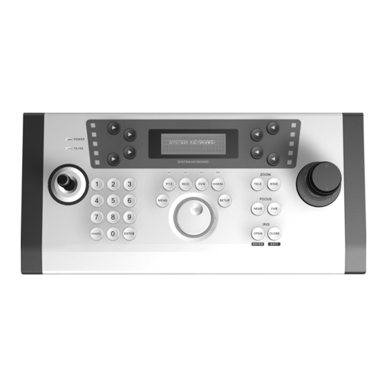
Chapter 1. Major functions and Features Chapter 1. Major functions and Features 1.1 Overview This product is designed to control PTZ CAMERA, DVR and other equipment by RS-485 or RS-422 1.2 Features 1) A long distance remote control It is possible to control equipment at a distance of 1.2Km by using RS-485. 2) System Control Camera(Receiver Unit) and DVR are controllable by one controller. - Page 7 Chapter 1. Major functions and Features ②Function ⑨Power ①LCD ⑤Main Joystick ⑧Mode Type 1 ④Sub Joystick ③Jog Type ⑦Number, Enter, Cancel ⑥Zoom, Focus, Iris ①LCD Display : Shows the information related to the operation. ②Function Key : There are 8 buttons(F1 ~ F8) to select functions. SUNKWANG CA M:001 Preset...
- Page 8 Chapter 1. Major functions and Features ⑦Number / Enter / Cancel Key : Enter the numeric values for PTZ or DVR menu setting. ⑧Mode Key : ㆍPTZ : Selects PTZ mode. ㆍMUX : Selects Mux mode.(It will be available in the future.) ㆍDVR : Selects DVR mode.(Available with the designated DVR) ㆍCAMERA :...
-
Page 9: Chapter 2. How To Install
Chapter 2. How to install Chapter 2. How to install 2.1 Environment for installation 1) Please read carefull to install the appliance with safety. 2) Please install the product on a completely flat floor or table. 3) Install the appliance in places where there are well ventilated. 4) It is strongly recommended to install the controller at environment as follow. -
Page 10: Product Components
Chapter 2. How to install 2 3 Product Components Junction Box Controller Cable Manual... -
Page 11: Chapter 3. System Connections
Chapter 3. System Connections Chapter 3. System Connections This chapter describes how to connect the controller with cameras, DVRs, multiplexers and other devices. 3.1 Connecting junction box and external device <Front> 12V DC Controller connection cable Junction Box <Back> Master Slave 1) Connecting with PTZ camera Connect TX+ and TX- terminals to the unit as the above picture. -
Page 12: Connecting With Dvr
Chapter 3. System Connections 2) Connecting with DVR Connect RS-485 converter to serial port of DVR(as above). ①Connection for Half Duplex - Connect TX(+) terminal on RS-485 converter to TX(+) terminal on the junction box. - Connect TX(-) terminal on RS-485 converter to TX(-) terminal on the junction box. ②Connection for Full Duplex - Connect TX(+) terminal on RS-422 converter to TX(+) terminal on the junction box. -
Page 13: Connecting Two Or More Controllers
Chapter 3. System Connections ②Connection for Full Duplex - Connect TX(+) terminal on RS-422 converter to TX(+) terminal on the junction box. - Connect TX(-) terminal on RS-422 converter to TX(-) terminal on the junction box. - Connect RX(+) terminal on RS-422 converter to RX(+) terminal on the junction box. - Connect RX(-) terminal on RS-422 converter to RX(-) terminal on the junction box. -
Page 14: General Connection
Chapter 3. System Connections ②Connection for Full Duplex - Connect TX(+) terminal on the junction box of the master controller to TX(+) terminal on the junction box of the slave controller. - Connect TX(-) terminal on the junction box of the master controller to TX(-) terminal on the junction box of the slave controller. -
Page 15: Multiple Keyboards To Multiple Devices
Chapter 3. System Connections 3) Multiple keyboards to multiple devices Master Slave... -
Page 16: Chapter 4. How To Use
Chapter 4. How to use Chapter 4. How to use 4.1 Log In 1) How to log in Log - in Password Input 4 d igit [ 0000 ] Factory default value is "0000" Press button and the followed picture will be shown. ENTER S UNKWANG CAM:001... - Page 17 Chapter 4. How to use NE W PAS SWORD Input NE W PAS SWORD [ 0000 ] Enter new passwords and press button. ENTER Please remember passwords. In case of forgetting your passwords. < > Log - in Password Input 4 d igit [ 1 897 ] Enter "1897"...
-
Page 18: Infomation
Chapter 4. How to use 4.2 Infomation Press button and LCD on controller will be shown as follow. The information would be different according to the camera. SUNKWANG CAM:001 Preset Patter n AutoPan ScanPan Stop Infomation Camera N umbe r :001 :Sunkwang Protocol... -
Page 19: Control Ptz
Chapter 4. How to use 4.3 Control PTZ 1) Select PTZ Push button and screen will be shown as follow. SUNKWANG CAM:001 Preset Pattern AutoPan Au x ScanPan Stop Press 'F5' button to activate cursor. CAM:001 SUNKWANG Preset Pattern AutoPan Au x ScanPan Stop... - Page 20 Chapter 4. How to use Basic screen displays according to the protocol. Screen displays would be different according to the protocol as follow. SUNKWA NG CAM :0 01 PELCO D CAM: 001 Preset Pattern Preset Pa ttern _________ A ut oPan Au x A ux _________...
-
Page 21: Camera Setting
Chapter 4. How to use 2) Camera Setting This menu is for setting one or more PTZ units for operation by the controller. Push PTZ button and screen will be shown as follow. S UNKWANG CAM:001 Preset Pattern AutoPan Au x ScanPan Stop Push SETUP button to go to 'SETUP' menu. - Page 22 Chapter 4. How to use CAM:001 CAME RA Protocol SK -P Baudrate 2400bps Format Sa ve Press F5 button to select PTZ. Input a PTZ camera number by numeric key(0~9). Saved setting value will be shown. Press F6 button to select protocol. Press F7 button to select baud rate.
-
Page 23: Preset
Chapter 4. How to use 3) Preset - Set the specific position and move to the memorized position Push button and screen on the controller will be shown as follow. S UNKWANG CAM:001 Preset Pattern AutoPan ScanPan Stop Press 'F2' button to select 'Preset' PRESET CAM:001 SPD:000... - Page 24 Chapter 4. How to use In case of PELCO protocol, screen will be shown as the followed picture. PRESET CAM:001 ________ NUM :000 ________ ________ SAVE MOVE <Preset Movement> PRESET CAM:001 SPD:000 NUM :000 DWL:000 Group:0 SAVE MOVE Press 'F6' buttion and input the preset number. PRESET CAM:001 SPD:000...
- Page 25 Chapter 4. How to use PRES E T CAM:001 SPD:020 NUM :000 DWL:005 Group:1 SAVE MOVE Press 'F2' button to input the preset speed. Press 'F3' button to set dwell time. Press 'F7' button to input a group number. Notice : Some functions would be not selectable according to protocol. Preset setup is also available in the OSD menu of the connected PTZ camera.
-
Page 26: Auto Pan Mode
Chapter 4. How to use 4) Auto Pan Mode This menu is for setting the camera panning automatically at the fixed speed. AutoPan Initialize all setting values. [SPD:005] Set the panning speed.(Default value : 5) [Custom] Select the type of AutoPan mode.(Default : Custom) [Start] Operate AutoPan mode [CAM:000] Set the camera No.(Protocols are not changed) - Page 27 Chapter 4. How to use Press button to control the panning speed. Max.20 levels are selectable. Higher number means higher speed. AutoPan CAM:001 SPD:005 1st:0 00 Custom 2nd:000 Star t Stop Press button to set the type of AutoPan mode. You can choose [Custom], [CW], or [CCW].
-
Page 28: Scan Pan Mode
Chapter 4. How to use 5) Scan Pan Mode This menu is to move the camera to the memorized positions one by one or randomly. The minimum of two PRESETs should be saved for this mode. Scan Pan Initialize all setting values. [------] No function [SEQ]... - Page 29 Chapter 4. How to use Select "SEQ" or "RANDOM" mode to operate. Scan Pan CAM:001 _________ _________ Group:1 Star t Stop Press button to select the group. Scan Pan CAM:001 _________ _________ Group:1 Star t Stop Press button to execute the operation. Scan Pan CAM:001 _________...
-
Page 30: Pattern
Chapter 4. How to use 6) Pattern ①This menu is for memorizing the position by panning, tilting, or zoom for a while and moving the camera to the memorized positions. See the camera manual for more information. ② Pattern Setup Push 'PTZ'button and the screen on the controller will be shown as follow. - Page 31 Chapter 4. How to use When 'F6' is selected, input the pattern number. 1~4 are selectable as a pattern number. PAT TERN CAM:001 _________ NUM:001 Star t Ru n Stop Press 'F3' button to set up 'PATTERN'. PAT TERN CAM:001 _________ NUM :001 Star t...
- Page 32 Chapter 4. How to use ③How to run PATTERN operation. PAT TERN CAM:001 _________ NUM:001 Star t Ru n Stop Check the pattern number. Press 'F7' button for pattern operation. PAT TERN CAM:001 _________ NUM :001 Star t Stop Press 'F8' button or move the joystick to stop pattern operation. PAT TERN CAM:001 _________...
- Page 33 Chapter 4. How to use [ST ART] - PATTERN SETUP - [ STOP ] - [RUN] - [END]...
-
Page 34: Aux Mode
Chapter 4. How to use 7) AUX Mode This function is to control AUX switch in case of any alarm on the cameras, Pelco and SK-P protocols only support this function. S UNKWANG CAM:001 Preset Pattern AutoPan Au x Stop ScanPan Press 'F7' button to select AUX mode. -
Page 35: Pattern Stop
Chapter 4. How to use 8) Pattern Stop This function is to stop memorizing pattern operation. S UNKWANG CAM:001 Preset Pattern AutoPan Au x ScanPan Stop... -
Page 36: Group Mode
Chapter 4. How to use 9) Group Mode ①This menu is for setting repeated sequential surveillance of assigned locations with assigned speed and intervals. See the camera manual for more information. ②Group Mode Push 'PTZ' button and the screen on the controller will be shown as follow. WONW OO CAM:001 Preset... - Page 37 Chapter 4. How to use Push 'F2' button to set the movement speed. GROUP Group1 SPD:000 Group2 DWL:000 Group3 Shift Group4 Push 'F3' button to set the dwell time. GROUP Group1 SPD:000 Group2 DWL:000 Group3 Shift Group4 Push 'F5' button to activate 'GROUP1'. Push 'F6' button to activate 'GROUP2'.
- Page 38 Chapter 4. How to use Push 'F4' button to select 'GROUP5' to 'GROUP8'. GROUP Group1 SPD:000 Group2 DWL:000 Group3 Shift Group4 Upon pushing 'F4' button, 'GROUP1 ~ GROUP4' and 'GROUP5 ~ GROUP8' are replaced each other. GROUP Group5 SPD:000 Group6 DWL:000 Group7 Shift...
-
Page 39: Tour Mode
Chapter 4. How to use 10) Tour Mode This menu is for setting one or more Groups for Tour so that continuous Group operations can be carried out. Push 'PTZ' button and the screen on the controller will be shown as follow. WONW OO CAM:001 Preset... -
Page 40: Control Dvr
Chapter 4. How to use 4.4 Control DVR 1) Control DVR Mode Press button and the followed picture will be shown. Display Backup RE W Search PL AY Menu STOP [Display] Select display division mode [Backup] Backup key - T o setup backup mode [Search] Search key - To search recorded data [Menu]... -
Page 41: Dvr Setup
Chapter 4. How to use 2) DVR Setup Press button and then press button. SETUP DVR SE TUP MODE DVR ID Protocol TB T BaudRate 4800 DVR ID : Select address of DVR(Default : 001) Protocol : Select type of protocol(TBT protocol only) BaudRate : Select baudrate of protocol(Default : 4800) *Support the DVR using TBT protocol only... -
Page 42: Chapter 5. Specification
Chapter 5. Specification Chapter 5. Specification Signal RS-485 / RS-422 Control Interface In/output terminal RJ-45 Baudrate 2400/4800/9600 Type 1 2 Axis 1ea, 3 Axis 1ea Joystick Type 2 Axis, 2ea 256 Camera ID Protocol setting Alarm setting Tilt Control Zoom operation Iris Focus adjust 64 preset setting... -
Page 43: Chapter 6. Q&A
Chapter 6. Q&A Chapter 6. Q&A 1. The camera can not be controlled. - Check the protocols of the cameras. 2. No screen. - Any shock might cause the malfunction. Please contact the place you purchased. 3. A button is pressed, but nothing is happened. - Check if you press another button simultaneously. - Page 44 Please read this manual carefully before installing and using the camera. Be sure to keep the manual handy for later reference. 3B05690C...
Need help?
Do you have a question about the SK-AR13 and is the answer not in the manual?
Questions and answers