Advertisement
Advertisement
Table of Contents

Related Manuals for Saga saga1-l4


Summary of Contents for Saga saga1-l4
- Page 1 INSTALLATION & OPERATION MANUAL...
- Page 2 SAGA1-L Series PREFACE This installation & operation manual is intended as an instruction manual for trained person who is in charge of installation, maintenance, repair, etc. Before installation please read the user’s guide and this installation & operation manual carefully.
-
Page 3: Table Of Contents
SAGA1-L Series The main contents of this manual are organized into the following chapters. Table of Contents PREFACE Wire Diagram of SAGA1-L series…………………………………………..p.4 2.0 Transmitter PCB Layout………………………………………………………..p.5 3.0 Receiver PCB Layout…………………………………………………………..P.6 3-1 Relay Board for SAGA1-L8, L6, L4, L8B, L6B 3-2 Independent COM Line 3-3 Receiver/Decoder Board for SAGA1-L8, L6, L4, L8B, L6B 4.0 Change of Frequency…………………………………………………………P.10... -
Page 4: Wire Diagram Of Saga1-L Series
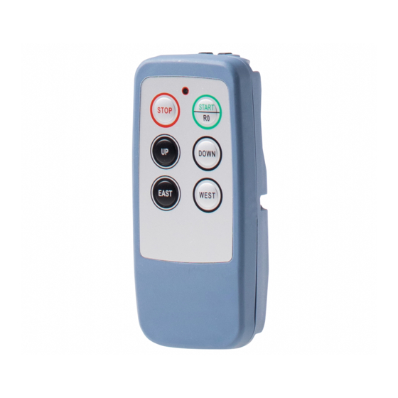
SAGA1-L Series WIRE DIAGRAM OF SAGA1-L SERIES: SAGA1-L8, L8B SAGA1-L6 SAGA1-L4 SAGA1-L6B Note: The polarity direction for Remark: (1) The R0/START could be N.C. or N.O. the power of DC12/24V (2) The fuse for the power AC24/48/110/220/380V is 0.5A. isn’t required when The fuse for the power DC12/24V is 1.5A. -
Page 5: Transmitter Pcb Layout
Replacing this Crystal to change the frequency on the transmitter. SAGA1-L4, L6, L8 SAGA1-L6B, L8B There are two kinds of frequencies VHF and UHF are available marking with a check is the current frequency band and please make sure not to replace a VHF crystal unit into UHF PC board or visa versa. -
Page 6: Relay Board For Saga1-L8, L6, L4, L8B, L6B
SAGA1-L Series RECEIVER PCB DIAGRAM: 3-1. Relay Board for SAGA1-L8, L6, L4, L8B, L6B 3-1-1 DC Type Fuse: 20A (yellow color) Fuse: 1.5A DC Input Remark: The polarity direction of DC Input isn’t required when plugging in the power line connector. - Page 7 SAGA1-L Series 3-1-2 AC Type Fuse: 10A Fuse: 0.5A Voltage selection Jumper: SAGA1-L8, L8B, L6B SAGA1-L6 HI position to AC Input select higher voltage of the combination, LO position to select lower voltage of the combination.
-
Page 8: Independent Com Line
“X” as showing as below. The longer part of the wire will become the new COM Line. Cut the SAGA1-L4 wire here. 3-2. Independent COM Line: The SAGA1-L series offer optional independent COM lines as: SAGA1-L8/L8B... -
Page 9: Receiver/Decoder Board For Saga1-L8, L6, L4, L8B, L6B
SAGA1-L Series 3-3. Receiver/Decoder Board for SAGA1-L8, L6, L4, L8B, L6B Replacing this There are two kinds of Crystal to Change frequencies VHF and UHF the frequency on are available marking with a the receiver. check is the current frequency band and please make sure not to replace a SQ ADJ is used for VHF crystal unit into UHF... -
Page 10: Change Of Frequency
SAGA1-L Series CHANGE OF FREQUENCY The frequency of SAGA1-L system can be simply changed by only replacing the correspondent crystal frequency in both the TX and RX. Please refer to below procedure in regards to replacing the crystal. Note: To replace a new crystal, please note that there are 2 kinds of frequencies (VHF and UHF) are available. - Page 11 SAGA1-L Series (4). Insert the new crystal unit vertically into the PC board. (5). Press the new crystal down into the socket. Attention: The frequency will be different when plugging the same crystal into the TX or RX. For example: T:311MHz Frequency for TX is 311 MHz R:321.7MHz...
- Page 12 SAGA1-L Series VHF BAND CONVERSION TABLE CH No. Ch-Freq(MHz) CH No. Ch-Freq(MHz) CH No. Ch-Freq(MHz) 310.0325 318.3250 326.6175 310.3000 318.5925 326.8850 310.5675 318.8600 327.1525 310.8350 319.1275 327.4200 311.1025 319.3950 327.6875 311.3700 319.6625 327.9550 311.6375 319.9300 328.2225 311.9050 320.1975 328.4900 312.1725 320.4650 328.7575 312.4400...
- Page 13 SAGA1-L Series UHF BAND CONVERSION TABLE CH No. Ch-Freq(MHz) CH No. Ch-Freq(MHz) CH No. Ch-Freq(MHz) 425.5925 433.8850 442.1775 425,8600 434.1525 442.4450 426,1275 434.4200 442.7125 426.3950 434.6875 442.9800 426.6625 434.9550 443.2475 426.9300 435.225 443.5150 427.1975 435.4900 443.7825 427.4650 435.7575 444.0500 427.7325 436.0250 444.3175 428.000...
-
Page 14: Change Of No/Nc Contact Of R0/Start Relay
SAGA1-L Series CHANGE OF NO/NC CONTACT OF R0/START RELAY The R0/START key of the new SAGA1-L crystal series provides NO and NC contact. The NO is the default setting. If a NC output is necessary, please remove the No. 8 wire (R0/Start, pink color) from the connector and insert it into No. -
Page 15: Id-Code Remote Setting
SAGA1-L Series ID-Code Remote Setting ID-Code remote setting allows you to pair the new TX or RX if one of them is damaged. In order to work the TX & RX must have the same frequency. Using ID-Code remote setting will make both the TX and RX to have the same ID Code. 1). -
Page 16: Troubleshooting
SAGA1-L Series TROUBLESHOOTING Item Phenomenon Cause Action Required Red LED flashing quickly a) One of the pushbutton a) Replace the (every 0.2 sec.) when is jammed. pushbutton. any motion pushbutton of b) The system is not b) Power on Transmitter is pressed. properly powered again according according to the... -
Page 17: Appendix
SAGA1-L Series Appendix SAGA1-L Series Software Installation and Operation Instruction I. How to install the SAGA1-L function setting program: 1. Insert the CD-ROM into the CD-ROM driver, the program initiates automatically, then you see a screen as below, click “OK” and continue: 2. - Page 18 SAGA1-L Series 4. Click “OK” to finish the installation procedure. II. How to start the SAGA1-L function setting program: To start using this program, please click from “Start” menu on your desktop, then move your mouse to “Programs”, “SAGA1-L SETUP PROGRAM”, and click on “saga1-L (CRYSTAL) SETUP PROGRAM”...
- Page 19 SAGA1-L Series leave this program (same as 2. On next toolbar “Tools” there are Read Setup Data to read the function setting of the transmitter or receiver (same as ); Write Setup Data to write function setting into the transmitter or receiver (same as );...
- Page 20 SAGA1-L Series IV. The operation of the program: Note: a. Make sure the power is off before any reading or writing either on the transmitter or receiver. b. Check the connection port on RS232 whether it is on “COM1” or others if the reading failed.
- Page 21 SAGA1-L Series 1. “Start Key” Function Setting Item Title Content Description This function is available only when remote controller is Normal “Power-On”. “Normal”: “R0” relay is on when “Start/R0” pushbutton is pressed or rotary key switch (for L6B, L8B) turned to “START”...
- Page 22 SAGA1-L Series 3. “Up / Down Pushbutton” Function Setting: Item Content Description “Normal/Normal (Interlock)”: When “Up” or “Down” is Normal/Normal (Interlock) Normal/Normal (Non-Interlock) pressed, if the other is pressed too, then both of them will be off. Normal/Toggle (Control by EMS) “Normal/Normal (Non-Interlock)”: Both of “Up”...
- Page 23 SAGA1-L Series “Enable”: Enable the transmitter to send EMS signal to Auto 1. Enable the receiver too before its own power is off. (Tx) 2. Disable “Disable”: Disable this function but the transmitter still will be power off itself if the “Save-Power” is executed. 1.
Need help?
Do you have a question about the saga1-l4 and is the answer not in the manual?
Questions and answers