Advertisement
one cool inverter.
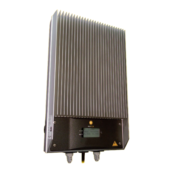
GT Series Solar Inverter Quick Install Guide v1.4
This quick installation
guide must be used in
conjunction
with
the
Installation Manual.
For installation support
contact
your
local
approved distributor.
All safety warnings must
be strictly adhered to.
If the inverter is installed
incorrectly, this will void
the warranty.
1.5kWGT / 2kWGT / 3kWGT / 3.8kWGT
Manufactured by: EnaSolar Limited
66 Treffers Road, Christchurch 8042, New Zealand
Tel +64-3-366 4550
|
Fax +64-3-366 0884
www.enasolar.net
See the next page before you begin.
Advertisement
Table of Contents

Summary of Contents for EnaSolar GT Series
- Page 1 GT Series Solar Inverter Quick Install Guide v1.4 This quick installation guide must be used in conjunction with Installation Manual. For installation support contact your local approved distributor. All safety warnings must be strictly adhered to. If the inverter is installed incorrectly, this will void the warranty.
-
Page 2: Before You Begin
Before You Begin. Before starting, you will need: • Notebook / PC running Microsoft XP or later. • Installation Utility (contact your distributor for login details). • Communications Cable, USB – USB Mini-B. • Customers SSID and passkey for their wireless router. As well as this Quick Install Guide a Installation Manual, Wall Mounting Template and Certificate of Conformity you will receive the following in the box... 1. - Page 3 1. Unpacking the Inverter. Undo the 4x screws, slide hands under the Inverter Module and lift to assist in removal of the Display Module. Then carefully disconnect the 3x cables from the display PCB (ground tab, communications cable, Wi-fi coaxial connector). Set the Display Module aside. Disconnect the 2x main inverter connectors by squeezing the side release tabs and carefully pulling out. Lift off the Inverter Module and then set aside. NEXT STEP 2. Wall Mounting Module.
- Page 4 2. Wall Mounting Module. Attach the provided Wall Mounting Template to the wall. Drill through the template in the specified locations, then remove the template from the wall. Fit the Wall Mounting Box to the wall using the supplied hardware. (minimum of 4x screws must be used.) Note: Eliminate the contact of dissimilar metals especially aluminium (wall mounting box) and any steel mounting hardware.
- Page 5 3. Wiring the AC & DC Connections. There are 4x DC input terminals (2x –VE & 2x +VE, as shown below). Both sets of inputs are connected in parallel, therefore when connecting 2x strings of PV panels, each string must be connected to an equal number of panels. It is best practice to connect the PV PV Earth Isolated (Default). panel frame to earth, run this cable along with the DC input and connect to the earth bar. Select the PV panel earth reference, the default setting is disabled (as shown). Positive Earth Fault Fuse. Negative Earth Fault Fuse. Wire the phase (fed from the circuit breaker in the switchboard), neutral conductors to their respective...
-
Page 6: Connecting The Inverter
4. Connecting the Inverter. Fit the Antenna by screwing in a clockwise direction. Refit the Inverter Module to the Wall Mounting Module. Reconnect the 2x main connectors (DC & AC). Then reconnect the 3x connectors to the Display Module PCB (the ground tab, the communication cable and the Wi-fi coaxial connector). At this point the Display Module can hang on the earth cable to allow configuration. NEXT STEP 5. Configuration. - Page 7 Further detail regarding the configuration process is available in the Installation Manual. Test the webpage by typing Enasolar-GT in the title bar of a web browser on a computer on the local network. NEXT STEP 6. Fitting the Display Module and Commissioning.
- Page 8 6. Fitting the Display Module and Commissioning. Disconnect the USB cable and fit the Display Module by screwing the 4x captive screws. Ensure that there are no cables that might get caught between the inverter module and the display module. After being certified by the lines distribution company, connect the AC to the unit. The Display module will display “Inverter Starting Up”, then “Connecting to the Grid in X secs” where X is the grid connect time. This will count down, then the inverter will start generating and display the green LED. For more detail see the full Installation Manual included.
Need help?
Do you have a question about the GT Series and is the answer not in the manual?
Questions and answers