
Related Manuals for Solar MPPT-10


Summary of Contents for Solar MPPT-10
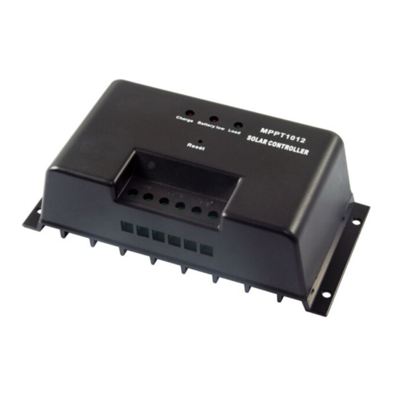
- Page 1 MPPT-10 Solar Charge Controller with Maximum Power Point Tracking Installation & Operation Manual...
-
Page 2: Table Of Contents
2.2 Structure....................4 2.3 Functions....................4 2.4 MPPT technology Instructions............6 3. PV System Planning Reference..............8 3.1 System Voltage..................8 3.2 Solar Modules Configuration...............8 3.3 Wire Sizing....................9 3.4 Over Current Protection..............10 3.5 Lightning Protection................10 3.6 Grounding....................11 3.7 System Expansion................11 4. - Page 3 Dear Consumer: Thank you very much for using our product! We will offer you the permanent and reliable service for your solar system! The manual gives important recommendations for installing and using the MPPT controller. Please read the manual carefully and...
-
Page 4: Safety Instructions
Tracking (MPPT) photovoltaic battery charge controller with our own technology. It’s main topology adopts in Buck conversion circuit, and uses MCU to adjust the solar panels working point intelligently in order to make the solar panels output its maximum power. When the circumstances change, the... -
Page 5: Structure
(1) Maximum Power Point Tracking technology The controller uses Buck conversion circuit and MCU technology to track the maximum power point to implement the maximum output power of solar panels in different illumination intensity and temperature. The MPPT algorithm increases efficiency of your PV system and decreases the quantity of solar panels. - Page 6 Connecting the solar modules with the controller by reserved connection will not damage the controller. The controller will work normally after connecting with correct polarity. (7) Reverse Current Protection The controller prevents reverse current from flowing into the solar modules...
-
Page 7: Mppt Technology Instructions
When the illumination intensity and solar panels temperature are fixed, the output power of solar panels is only affected by load impedance. Different load impedance will make the solar panels work at different point and put out the different power. - Page 8 Output voltage is 17.6V, output power is 92W. This point is the state when using MPPT controller. Because of using power conversion technology, the solar panels voltage is not clamped by battery and still works at maximum power point. Compare working point A & B, it is easy to find using MPPT controller can increase the using efficiency of solar panels.
-
Page 9: Pv System Planning Reference
3. PV System Planning Reference 3.1 System Voltage The common system voltage of solar system has 3 types: 12V, 24V and 48V. The higher the system voltage, the more power the system can handle. In reality application, user should consider the load power, and the voltage scope permitted by load, and then confirms which system voltage you should use. -
Page 10: Wire Sizing
Table 3-3: Solar Panels Model and System Configuration Solution 3.3 Wire Sizing The maximum input and output current of MPPT-10 is 10A. To ensure the cable temperature does not exceed the safety range, the copper cable’s area must be at least 2.5mm . -
Page 11: Over Current Protection
We suggest users to install over-current breaker or fuse on the negative loop of solar panels input, and also the negative loop of battery output. The capacity of over-current breaker or fuse is 1.25 times of the rated current. -
Page 12: Grounding
More controllers can share with one battery group, but each controller must be connected with the independent solar panels array and the independent load. (Please contact the local distributor for further information.) 4. Installation 1. -
Page 13: Connecting Diagram
Mounting hole pitch: 60mm*178mm Mounting hole diameter: Ф5mm Height*Width*Thickness: 92.5mm*188mm*55.3mm Connecting terminals: Maximum 6mm² 4.2 Connecting Diagram Temperature Sensor Fuse ③ ① ② Figure 4-2: Connecting Diagram 4.3 Wiring A、Choose the appropriate cables requested as Chapter 3. Prepare 4 sets of M5 screws (used to fix the controller on the wall or other vertical plane). -
Page 14: Installation Process
A. Mount the controller on the wall and fasten the screws. B. Check whether the battery voltage and solar panels array voltage is within the requested range. C. Switch off the over-current breaker or fuse of the battery, solar panels array and load. D. Wiring. -
Page 15: Led Displays
Load Short-circuit Protection T=0.5s 5.3 System Voltage Indication The MPPT-10 controller adjusts itself to 12V or 24V system voltage automatically. The system type indicates by the green led when the controller startup every time. Details show as follows: Figure 5-3: System Voltage Indication Diagram... -
Page 16: Protection Remedies
Possibly temperature reduce the charge current. Make sure the too high controller is adequately ventilated. Inside Disconnect the load, solar modules and temperature Load on battery. Re-install the controller. If the error sensor Charging on recurs, then please contact your specialist error dealer. -
Page 17: Common Faults And Remedies
The polarity. fuse burns out. Battery The controller Disconnect the load, solar modules overvoltage adjusts to the and battery. Waiting for about 10 protection wrong system seconds then... -
Page 18: Technical Data
7. Technical Data Model MPPT-10 Maximum PV voltage ≤70V Input 12V~70V (12V) MPPT voltage range 24V~70V (24V) System voltage 12V (24V) Maximum battery voltage 16V (32V) Maximum charging current Maximum load current Own consumption ≤15mA Charging control mode 3-stage (Bulk, Absorption, Float)
Need help?
Do you have a question about the MPPT-10 and is the answer not in the manual?
Questions and answers