Inovonics EN4216MR Installation And Operation Manual
16 zone multi-condition
receiver with relay outputs
Hide thumbs
Also See for EN4216MR:
- Installation and operation manual (6 pages) ,
- Installation and operation manual (6 pages)
Table of Contents
Advertisement
Quick Links
EN4216MR 16 Zone Multi-Condition
Receiver with Relay Outputs
Installation and Operation Manual
1 Overview
The EN4216MR receiver allows you to add up to 16 transmitters and six
outputs to any application, and includes a housing tamper for increased
tamper security.
The following add-on receivers are available from Inovonics:
Alarm Output
Receiver
Relays
EN4204R
4
EN4216MR
5
EN4232MR
11
* At least one relay must be used for faults to ensure the system is
supervised. More than one relay may be used, but that will deduct from the
number of alarm output relays.
1.1 Installing an Inovonics Security System
An EchoStream survey kit must be used to establish a UL system. The
EchoStream survey kit measures the signal strength of high-power
repeater and sensor messages to help optimize your EchoStream system.
Figure 1 Sample EchoStream system
The EchoStream survey kit provides you with two signal strength
measurements: signal level and signal margin.
Signal level
The signal level is the measurement of the overall decibel level of the
message.
Signal margin
The signal margin is the measurement of the decibel level of the message,
minus the decibel level of any interfering signals. Inovonics Wireless
equipment should be placed within a facility such that all end-devices
produce signal margin readings of at least 4 decibels.
Both the signal level and signal margin are measured in decibels. Because
Signal Strength and signal margin are measured on a logarithmic scale, the
difference between a decibel level of 3 (Weak) and a decibel level of 4
(Good) is a much larger difference than it would be on a linear scale.
Note: For more information about the EchoStream survey kit, see the EN/
®
EE7016SK EchoStream
Survey Kit Installation and Operation Manual.
8/18/15 05637E © Inovonics, 2015 - www.inovonics.com
Transmitters
Fault Relays
Supported
1
4
1*
16
1*
32
1.2 Inovonics Contact Information
For product and installation videos visit us at
www.inovonics.com/videos or use the QR
code below.
If you have any problems with this procedure, contact Inovonics technical
services:
• E-mail: support@inovonics.com.
• Phone: (800) 782-2709; (303) 939-9336.
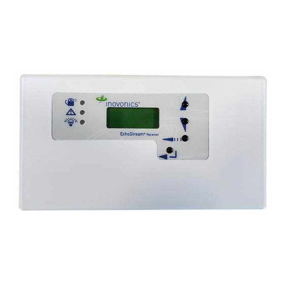
1.3 EN4216MR Front Panel
A
B
C
Figure 2 Receiver front panel
A Output LED
B Fault LED
D LCD display
E Up button
G Back button
H Enter button
Output LED: Lights when any transmitter output is active.
Fault LED: Lights when any transmitter is sending a fault condition.
Power LED: Lit when receiving power.
LCD Display: Shows status, event log and programming information.
Decode LED: Flashes when any recognizable transmission is received.
This LED is only visible when the cover is removed.
Up button: Scrolls the display up.
Down button: Scrolls the display down.
Back button: Returns display to the previous menu, or when pressed in
the main menu options, returns the unit to normal operating mode. When
entering information in the display, returns to the last character entered.
Enter button: Selects the currently displayed menu item. If in normal
operating mode, sets the unit to menu mode.
Reset button: Clears the current status for all points and resets all outputs
and LEDs. Records a receiver reset entry in the event log and resets the
supervision window timers. This button is only accessible when the cover is
removed.
D
E
F
G
H
C Power LED
F Down button
Advertisement
Table of Contents

Subscribe to Our Youtube Channel
Related Manuals for Inovonics EN4216MR


Summary of Contents for Inovonics EN4216MR
- Page 1 QR code below. 1 Overview The EN4216MR receiver allows you to add up to 16 transmitters and six outputs to any application, and includes a housing tamper for increased tamper security. The following add-on receivers are available from Inovonics:...
- Page 2 Note: For UL listed systems containing a UL hold-up switch, the J Reset button K Decode LED EN4216MR must be located within three feet of a system keypad in a location out of sight from the protected premise. 1.5 What’s in the Carton •...
- Page 3 EN1265* Motion To access the point status menu: 1. From the EN4216MR start screen, press the enter button to access the * Device has not been evaluated by UL for compatibility. receiver’s three main menus. “Point Status” displays. 2. Press the enter to display point status details.
- Page 4 Register Transmitter: The register transmitter option allows you to individual condition. For more information, see Table 1:, “EN4216MR register a transmitter or repeater to the programmed point. Supported Transmitters”.
- Page 5 “Factory Config” on page 5. 4.5.6 Factory Config The factory config option is used to restore the EN4216MR to its factory defaults. Caution: Choosing factory config will erase all programmed point and output information, as well as the password.
- Page 6 8 ADT Focus 200 Plus / Focus Cadet Control Panel Wiring and Programming Information 8.1 Typical EN4216MR Receiver Connection to ADT Focus 200 Plus / Focus Cadet Control Panel EN4216MR Function EN4216MR Panel Terminal Keypad Text Terminal Power in (12V DC)
- Page 7 11 (HU) Holdup Note: For UL installations, the control panel must be programmed to indicate an alarm if the system is in an armed condition and an RF jamming signal occurs at the receiver. 8/18/15 05637E © Inovonics, 2015 - www.inovonics.com...
- Page 8 9 Bosch D9412GV2 / D7412GV2 Control Panel Wiring and Programming Information 9.1 Typical EN4216MR Receiver Connection to Bosch D9412GV2 / D7412GV2 Control Panel EN4216MR Function EN4216MR Panel Terminal Keypad Text Terminal Power in (12V DC) (3) + Aux Power Ground...
- Page 9 Silent bell = Yes Note: For UL installations, the control panel must be programmed to indicate an alarm if the system is in an armed condition and an RF jamming signal occurs at the receiver. 8/18/15 05637E © Inovonics, 2015 - www.inovonics.com...
- Page 10 10 DMP XR500 Control Panel Wiring and Programming Information 10.1 Typical EN4216MR Receiver Connection to DMP XR500 Control Panel EN4216MR Function EN4216MR Panel Terminal Keypad Text Terminal Power in (12V DC) (7) RED Ground (10) BLK NC (1) Alarm 1...
- Page 11 Status List must not have panic zone keypads enabled Note: For UL installations, the control panel must be programmed to indicate an alarm if the system is in an armed condition and an RF jamming signal occurs at the receiver. 8/18/15 05637E © Inovonics, 2015 - www.inovonics.com...
Need help?
Do you have a question about the EN4216MR and is the answer not in the manual?
Questions and answers