
Subscribe to Our Youtube Channel
Summary of Contents for John Bean BFH 1000
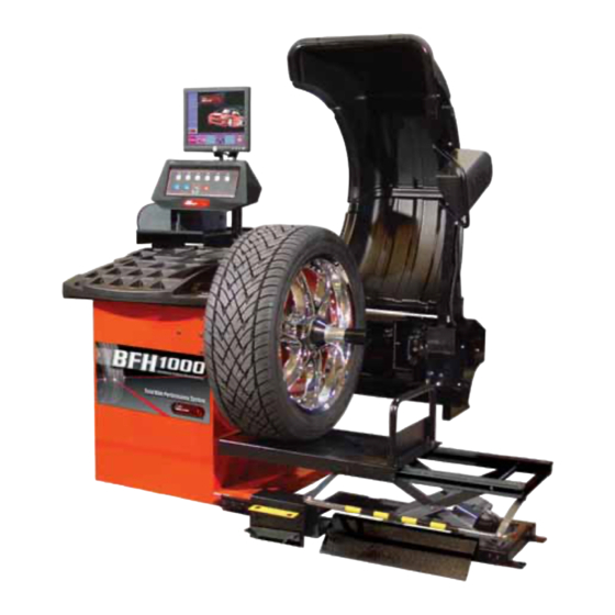
- Page 1 COMPUTER RIDE DIAGNOSTIC WHEEL BALANCER OPERATION INSTRUCTIONS Form ZEEWB519A rev C July, 2006...
- Page 2 Blank page...
-
Page 3: Safety Information
It is assumed that, prior to using the BFH 1000 or BFH 1000 Super Ride Diagnostic Wheel Balancer, the operator has a thorough understanding of the wheels and tires being serviced. -
Page 4: Important Safety Instructions
IMPORTANT SAFETY INSTRUCTIONS When using this equipment, basic safety precautions should always be followed, including the following: Read all instructions. Do not operate equipment with a damaged power cord or if the equipment has been damaged - until it has been examined by a qualified authorized service technician. If an extension cord is used, a cord with a current rating equal to or more than that of the machine should be used. -
Page 5: Table Of Contents
8.0 BFH 1000 Procedures ......................23 8.2 Begin Diagnostic Run ......................23 8.2 Profiling the wheel ........................23 8.3 BFH 1000 Geometric Matching ....................25 8.4 Bare Rim Diagnosis ......................... 27 9.0 OptiLine, Balancing a Set of Wheels ..................28 9.1 OptiLine Customer Calibration .................... -
Page 7: Introduction
John Bean BFH 1000 Series Operators Manual 1.0 INTRODUCTION Congratulations on purchasing the BFH 1000 Series Computer Ride Diagnostic Wheel Balancer. This wheel bal- ancer is designed for ease of operation, accuracy, reliability and speed. With proper maintenance and care your wheel balancer will provide many years of trouble-free operation. -
Page 8: Safety Notice
1.2 BALANCER APPLICATION The John Bean BFH1000 Series Ride Diagnostic Wheel Balancer is intended to be used as a device to balance, diagnose and correct car, and light truck wheel vibration problems within the following range: Maximum tire diameter 44”... -
Page 9: Features
• Operator selectable round-off mode. • Wheel pull index, option (standard on BFH 1000 Super) • Wheel runout in multiple positions, optional feature (standard on BFH 1000 Super) • Premium 7 cone set with storage tray option (standard on BFH 1000 Super) Page 3... -
Page 10: Standard Accessories
1.5 STANDARD ACCESSORIES Standard accessories ( Figure 1) included with the Standard BFH 1000 are: EAM0003J08A Cone, 85-132 mm / 3.3”-5.2” EAM0003J07A Cone, 71-99 mm / 2.8”-3.9” EAM0003J06A Cone, 56-84 mm / 2.2”-3.3” EAM0003J05A Cone, 43-63 mm / 1.7” - 2.5”... -
Page 11: Optional Accessories
John Bean BFH 1000 Series Operators Manual 1.6 OPTIONAL ACCESSORIES - SEE FIGURE 2 Wheel Lift - EAK0221J27A Printer Kit - EAK0221J26A Flange Plate Cart EAS2081J30A Stick-on Weight Removal Tool Flange Plates - Kit of 4 7 Cone Set - EAK0221J31A... -
Page 12: Installation Area Requirements
B. Install the Cone Accessory tray if installing a BFH 1000 Super Model. See Figure 4b. Figure 4a - BFH 1000 Figure 4b - BFH 1000 Super C. Place accessories onto the accessory pins or place 7 cone set into tray if installing a BFH 1000 Super. Page 6... -
Page 13: Electric Installation
John Bean BFH 1000 Series Operators Manual 2.1 ELECTRIC INSTALLATION ANY ELECTRICAL WIRING MUST BE PERFORMED BY LICENSED PERSONNEL. ALL SERVICE MUST BE PERFORMED BY AN AUTHORIZED SERVICE TECHNICIAN. Check on the plate of the machine that the electrical specifications of the power source are the same as the machine. - Page 14 Figure 5a - Complete Function Menu listing Page 8...
-
Page 15: Customizing Optima Features
John Bean BFH 1000 Series Operators Manual 2.2.2 CUSTOMIZING OPTIMA FEATURES • From the “Welcome” Screen or Balance Screen, select the “F6” Optima button. • Select the “F3” Key to enter the menu used to set the limits required for an Optimization procedure. -
Page 16: Physical Layout
3.0 Physical Layout. Refer to Figure 7. - Functional description of the unit: 1. The screen 2. Input panel 3. Gauge arm 4. Stub shaft with power clamp nut 5. Brake pedal 6. Weight compartments 7. Storage areas for cones or clamping devices 8. -
Page 17: Menu Keys
3.2 Menu Keys 3.2.1 Description of Menu Keys The assignment of the menu keys F1 to F6 is shown in the menu fields above the relative keys on the screen. The menu keys have different functions and initiate different actions, depending on the program step. -
Page 18: Main Menu Functions
3.2.2 MAIN MENU FUNCTIONS Icon 1 Change to the Function screen Icon 2 Perform adapter compensation run Icon 1 Icon 2 Icon 3 Change to the Balancing screen Icon 4 Change to the OPTIMIZATION MENU Icon 3 Icon 4 3.2.3 BALANCING Icon 5 Toggle switch, two functions: Pressed on top: View and/or edit Data Input (wheel parameters) - Page 19 3.2.4 RIM DATA INPUT Icon 11 Change to the WEIGHT PLACEMENT (mode) screen. Icon 12 Change to the RIM TYPE screen Icon 12 Icon 11 Icon 13 Hold key down and enter the distance rim/ machine by rotating the wheel Icon 14 Hold key down and enter the rim width by rotating the wheel Icon 15 Hold key down and enter rim diameter by...
-
Page 20: Function (Setup)
3.2.7 TEXT EDITOR Icon 23 Change to the screen TEXT EDITOR Icon 24 Toggle key, four functions: Move the cursor within the character set (right, left, up, down) to the desired character. Icon 23 Icon 24 Icon 25 Toggle key, four functions: Move the cursor within the text field (right, left, up, down) to the desired text box location Icon 26 Transfer characters from the character set to... -
Page 21: Help Information
4.0 Help information Help information explains the current action and, in the case of an error code, provides hints for remedy. See Figure 11. Display help information Figure 11 • Press the HELP key ( See Figure 12) The first screen with help information appears, e. g. to the screen RIM DATA INPUT. -
Page 22: Power Clamp
Push down for brake 5.0 POWER CLAMP 5.1 POWER CLAMP PEDAL Shaft Lock The main shaft is locked when the pedal is depressed. This holds the wheel in the correction position for correct fitting of the correction weights. See Figure 13. This lock is designed only to facilitate orientation of the wheel and must not be used for braking the main shaft. -
Page 23: Operation Of The Balancer
6.0 OPERATION OF THE BALANCER WARNING: For operator safety please read and follow the precautions outlined on pages 1 and 2 of this manual. NOTE: READ ALL INSTRUCTIONS BEFORE PROCEEDING WITH OPERATION OF THE BAL- ANCER All balancer functions are input into the main computer through the large easy to read touch panel. Although each wheel tire assembly differ in some ways all balancing jobs require basically the same procedure. -
Page 24: Balance Screen Description
John Bean BFH 1000 Operators Manual 6.2 BALANCE SCREEN DESCRIPTION Refer to Figure 16a below for an example of a typical balance screen. The wheel displayed has been profiled as a rim which will accept a clip weight on the left side and a stick-on weight on the right side. -
Page 25: Wheel Mounting
An incorrect centering of the wheel will result in considerable imbalance. There are many types of wheels and John Bean supplies adaptors of high quality and durability for the large majority. However if you meet special wheels which may require a specific adaptor, call your authorized John Bean distributor. -
Page 26: Scan Mode Selection
6.3 SCAN MODE SELECTION The BFH 1000 can be operated in 2 automatic scan modes and one manual mode. Default factory setting is the OPTIMA mode. The BFH 1000 can easily be set to PROFILING mode if OPTIMA functionality is not required or wanted for every balance job. -
Page 27: Spinning The Wheel
6.4 SPINNING THE WHEEL NOTE: Before spinning the wheel, make sure proper eye protection is worn by all personnel in the vicinity of the balancer. A. Spin the wheel by lowering the wheel guard. If auto-spin is not activated press “Start” to begin balancer run. When the balancing cycle is complete the wheel will stop automatically and the imbalance values will appear on the screen. -
Page 28: Correction Of The Imbalance
John Bean BFH 1000 Operators Manual 6.6 CORRECTION OF THE IMBALANCE A. The wheel assembly automatically stops near the right weight correction plane. NOTE: Automatic plane braking can be selected from the main function setup menu. Factory default is right plane (2), select a value of “1”... -
Page 29: Vibration Problems
D. If an ALU function was selected ensure the wheel weights have been placed in accordance to the program chosen. E. Check that the wheel is not slipping against the backing collar. F. Check that the wheel and adaptors are clean. Graphic 1. -
Page 30: Bfh 1000 Procedures
John Bean BFH 1000 Operators Manual 8.0 BFH 1000 Procedures BFH 1000 MODE is a feature which improves wheel running conditions through enhanced optimization capabilities while improving wheel balancer productiv- ity without the need to measure the radial force. In the BFH 1000 mode the following parameters are measured in one measuring run only: •... - Page 31 Calculations are made with all input data and stored for display when recalled. Figure 25 If BFH 1000 thresholds have been exceeded the BFH 1000 Diagnostics screen will indicate the assembly radial runout amount and make a recommendation of performing a full BFH 1000 compensation procedure.
-
Page 32: Bfh 1000 Geometric Matching
John Bean BFH 1000 Operators Manual 8.3 BFH 1000 Geometric Matching Select softkey “F5” to continue to the matching process if desired. See Figure 27. Rotate the assembly so the valve stem is located at top dead center. Press “F6”, to continue. See Figure 28. - Page 33 1000 screen would be displayed with additional sugges- tions. See Figure 33. Figure 33 If the assembly passed this time the BFH 1000 display would say “OK”. If a problem is detected, the information is displayed on the diagnostics screen. See Figure 34, the example indicated a high runout on the wheel, BFH 1000 procedures are not possible.
-
Page 34: Bare Rim Diagnosis
See Figure 35. Figure 35 8.4 Bare Rim Diagnosis The BFH 1000 has the ability to automatically detect the presence of a bare rim when mounted. The unit will then measure both bead seat surfaces for radial runout . -
Page 35: Optiline, Balancing A Set Of Wheels
NOTE: This feature is not available as stan- dard with the BFH1000 wheel balancer but is to be purchased in addition. On the BFH 1000 wheel balancer the outer tire surface is scanned by the lasers and the result calculated into a pull index. After 4... - Page 36 Now the 2nd wheel can be clamped and the measuring run started. Depending on the measurements the BALANCING screen or the BFH 1000 ENTRY screen will come up. After the wheel has been matched and / or the im- balance has been corrected the wheel is...
- Page 37 The proposal for the position of the wheels on the car is given to reduce the pull as much as lowest run out possible. Should the operator want to posi- tion the wheels in a way that the lowest vibra- tion is achieved on the steering wheel he Figure 47 presses the F6 button.
-
Page 38: Optiline Customer Calibration
John Bean BFH 1000 Operators Manual 9.1 OptiLine Customer Calibration The T shaped calibration tool supplied with the OptiLine kit is required for checking and correcting any parallelism disparity between the rear scanner plane and the axis of the ma- chine wheel shaft to guarantee precision measurement of the tread conicity indices. - Page 39 Turn the front surface of the Tool towards the back of the balancer, angle the plate towards the scanner, approximately 5 degrees downward, then lock it in position using the pedal brake. Lower the wheel guard. Press F6 to start calibration (foot pedal can be released). The rear scanner will traverse to the right starting the calibration.
-
Page 40: User Calibration
John Bean BFH 1000 Operators Manual 9.0 USER CALIBRATION The BFH 1000 Balancer features a user calibration program which requires only a few minutes to complete. Perform this procedure when the balancer has been moved, disturbed, or whenever accuracy is questioned. Occasional field calibration will ensure years of reliable service. -
Page 41: Explanation Of Program Codes
10.0 EXPLANATION OF PROGRAM CODES In the event of damage or malfunction, a code may be displayed indicating the area or location of the detected error. These codes are important to the service agent when he services the unit. Note any codes or error messages before calling for service or assistance. - Page 42 John Bean BFH 1000 Operators Manual A. Hardware test -common errors C10F02 -Test returned with an error. No valid test results available C10F07-Test function reported an unkown error C10F18-Test timed out. No valid test results available B. Hardware test -Power supply voltage...
-
Page 43: Maintenance
11.0 MAINTENANCE BEFORE ANY MAINTENANCE OR REPAIRS ARE ATTEMPTED THE MACHINE MUST BE DIS- CONNECTED FROM THE ELECTRIC SUPPLY. This balancer does not require any special maintenance, but the following precautions are required: A. Periodically clean all plastic parts with a glass cleaner. Wipe with a dry cloth. B. - Page 44 NOTES...
- Page 45 NOTES...
- Page 46 ® CANADA Equipment Services John Bean 309 Exchange Avenue 6500 Millcreek Drive Conway, Arkansas 72032 Mississauga, Ontario Tel.: (800) 362-8326 or (501) 450-1500 Canada L5N 2W6 Fax: (501) 450-1585 Tel: (905) 814-0114 Fax: (905) 814-0110 UNITED KINGDOM FRANCE UK Equipment Ltd...
Need help?
Do you have a question about the BFH 1000 and is the answer not in the manual?
Questions and answers