Table of Contents
Advertisement
Quick Links
Advertisement
Table of Contents

Summary of Contents for Motec Systems C125
- Page 1 C125 Display Logger USER MANUAL...
- Page 2 MoTeC C125 User Manual Copyright 2015 – MoTeC Pty Ltd The information in this document is subject to change without notice. The supplied product may differ slightly to the images While every effort is taken to ensure correctness, no responsibility will be taken for the consequences of any inaccuracies or omissions in this manual.
-
Page 3: Table Of Contents
C125 Race Kits ............... 12 C125 Race Display Kit ..............12 C125 Race Logging Kit ..............12 Installing the C125 Terminated Loom ..........13 Installing the C125 Input Loom ............14 Installing the OBD-II To Display Loom ..........15 Installing the CAN ECU To Display Loom ......... 16 Installing the RS232 ECU To Display Loom ........ - Page 4 Display Logger Upgrades ..............59 Characteristics ................. 60 Input Characteristics .............. 60 Output Characteristics ............65 C125 Pin List by Pin Number ............66 C125 Pin List by Function ..............67 Mounting Dimensions ..............69 Wiring ....................70 Connector ................70 Wire Specification ..............
- Page 5 C125 User Manual MoTeC C125 Display Logger to ECU wiring (RS232)......73 C125 Loom Wiring ..............74 Update Rate Summary..............75 Command Line ................77 CAN Bus Bandwidth Limit ..............79 Comms Error Codes ................ 80 Windows Keyboard Shortcuts ............83 Screen Cleaning ................
- Page 6 MoTeC C125 User Manual...
-
Page 7: Introduction
Introduction C125 - Club Display Logger The C125 is a sophisticated display and powerful control device combined in one lightweight unit. With the addition of a Data Logging upgrade it becomes a fully programmable data logger with 120 MB memory (see Display Logger Upgrades). - Page 8 MoTeC Introduction • Configurable to use sensors from some existing engine management systems Display • Colour TFT LCD, anti-reflective • 12 customisable layout options • Customisable measurement units and warnings • Configurable dial, sweep or bar graph can display any channel with optional peak, hold and shift markers •...
-
Page 9: System Overview
Typical devices used with the Display Logger ECUs The C125 Display Logger can be connected to all MoTeC engine management systems and some other manufacturers' ECUs either via CAN, RS232 or OBD-II. This avoids duplication of sensors and allows the Display Logger to display and log many ECU parameters. - Page 10 Analogue Temperature input. However most wheel speed sensors generate a variable frequency signal which must be connected to either a Digital input or a Speed input. *To use these inputs, you will need to add the #29600 C125 I/O enable. Expanders E888/E816...
- Page 11 Bosch LSU 4.9 / NTK Lambda sensors and transmit Lambda readings via the CAN bus. Remote Displays A remote display device may be connected to the C125 to allow display of any value that the Display Logger calculates, such as lap times and warning alarm messages.
- Page 12 CAN to the Display Logger. Several models are available to suit vehicles with different complexity ranging from 15 to 32 outputs and 12 to 23 inputs. Other Devices Many other devices can be connected to the C125 Display Logger.
-
Page 13: C125 Race Kits
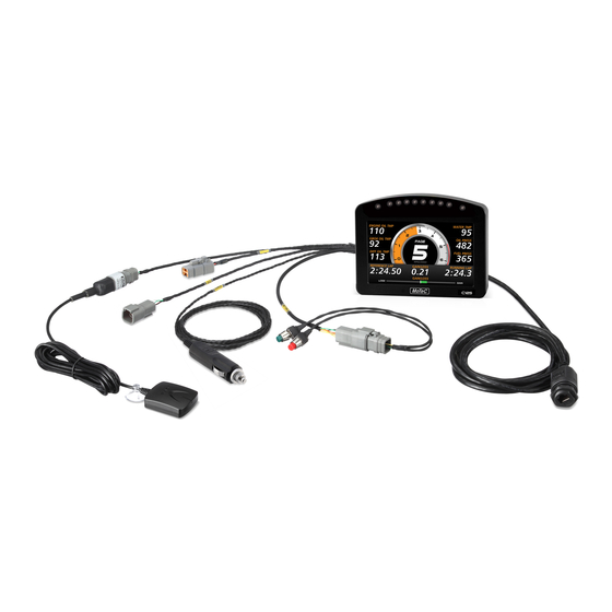
C125 Race Kits C125 Race Display Kit The C125 Race Display Kit is a complete plug and play solution. All wires are labelled and terminated, ensuring a fast, easy installation. The Race Display Kit will allow you to perform the following functions and more with your C125: •... -
Page 14: Installing The C125 Terminated Loom
The C125 has an optional terminated loom that is pre-configured to get the most out of your Display Logger. This loom plugs directly into the back of the C125, and has labelled wires for each of the parts that come with the Race Kit. The loom has these connections: •... -
Page 15: Installing The C125 Input Loom
MoTeC Installing the C125 Input Loom The C125 Input loom is a fast way to add sensors to your C125 when you have added the I/O upgrade. Following these instructions, you can quickly add wiring for 6 AVs, 2 ATs, 2 Digital and 3 Speed inputs to your vehicle’s loom. -
Page 16: Installing The Obd-Ii To Display Loom
Installation method – if C125 came pre-configured 1. Plug in the C125, buttons and GPS. DO NOT connect the OBD-II To Display Loom at this stage. 2. Plug the cigarette lighter power adapter into a spare power supply socket. -
Page 17: Installing The Can Ecu To Display Loom
Installation method – if C125 came pre-configured 1. Plug in the C125, buttons and GPS. 2. Connect the C125 to CAN ECU adapter loom to the ECU plug on your C125 loom. Plug the other end into your ECU communications connector. - Page 18 10. Select OK on the Connection settings screen. 11. Select File > New 12. Select C125 M400 M600 M800 template if you have one of those ECUs, or select the C125 M84 template. 13. Select Online > Send Configuration to put the configuration in the Dash 14.
-
Page 19: Installing The Rs232 Ecu To Display Loom
C125 Track Kits MoTeC Installing the RS232 ECU To Display Loom The RS232 ECU To Display Loom connects the C125 loom to an ECU via its RS232 communications connector. NOTE: The RS232 communications connector is the socket that you would normally use to connect to your ECU for tuning. - Page 20 10. Select OK on the Connection settings screen. 11. Select File > New 12. Select C125 M4 M48 template if you have one of those ECUs. Other ECUs will require a custom template. 13. Select Online > Send Configuration to put the configuration in the Dash.
-
Page 21: Installation
20 degrees, however the Display Logger will provide good contrast between 0 and 40 degrees. Display reflections should also be considered when determining the mounting angle. The C125 uses a 34 pin connector. See Connector C125 Pin List by Function for full details. -
Page 22: Connecting Devices
PC can communicate with the Display Logger without the need to power the rest of the vehicle. • The C125 ground must have a direct connection to the vehicle battery. • The Display Logger is connected to other devices via the CAN bus. - Page 23 Installation MoTeC o Signal conditioned three-wire pressure sensors o Thermocouple amplifiers o Accelerometers These inputs can also be used to measure two-wire variable resistance sensors if an external pull-up resistor is connected from the input to the 5 V sensor supply. Additionally, on/off switch signals may be connected, which may also require an external pull-up resistor.
-
Page 24: Outputs - Requires I/O Upgrade
MoTeC Installation Speed Inputs Speed Inputs are identical to Digital Inputs except that they can also be configured to suit Variable Reluctance (Magnetic) sensors, such as some wheel speed sensors. Because the amplitude of the signal from these sensors changes with speed of rotation, variable trigger levels are required, which must vary with the frequency of the input signal. -
Page 25: Communications
CAN (Controller Area Network) Communications This protocol enables communication between all devices connected to the same bus. The CAN bus allows for communicating at high speeds. The C125 has two independent CAN communications ports that can be connected to other devices with a compatible CAN port. The bus speed for each interface can be set independently. -
Page 26: Connecting Devices Examples
MoTeC Installation Connecting Devices Examples Device Connect via Remarks Inputs: Sensors MoTeC supplies datasheets The appropriate input with wiring details for all type depends on the sensors via the website sensor type Inputs: External Buttons for: Wire between Display - Display mode Digital or Speed inputs Logger input and Display - Display next line... -
Page 27: Software Installation
3. When downloading is finished, double click on the file and select run 4. Follow the instructions on the InstallShield Wizard 5. To start the program after installation, click the C125 Dash Manager icon on the desktop or click Start > All Programs > MoTeC > C125 > C125 Dash Manager... -
Page 28: I2 Data Analysis Software
The Display Logger connects to the Ethernet port on the PC. This requires a connector for the standard Ethernet cable in the loom. The C125 loom 62204 incorporates this connector. Alternatively the connector can be wired into an existing loom using the unterminated Ethernet cable (61131), or the Ethernet to Superseal Connector Cable that is terminated with Tyco connector pins (61236). - Page 29 Installation MoTeC If the Device is 'discovered' without the anti-virus software, you can turn it back on and put in appropriate exceptions to allow the Display Logger Manager to communicate with the device. Only one connection can be active at a time. To switch to a different Display Logger, click Make Active.
-
Page 30: Configuration
MoTeC Configuration Configuration All aspects of the Display Logger can be configured, including; which sensor is connected to which input, the calibration of each sensor, what to display and where to display it, what to log and how fast to log it, tacho range, warning alarms, multi stage shift lights etc. -
Page 31: Channels
Configuration MoTeC • Edit Details – allows for entering event, venue and vehicle details to be stored with the configuration file • Check Channels – verifies that all channels are correctly generated • Edit Configuration Comments – allows for other comments to be stored with the configuration file •... - Page 32 MoTeC Configuration These general purpose channels may be required when measuring an uncommon value, or when a general purpose function needs to generate a special output channel. For example, a 3D table may generate an output channel to control a valve of some sort, in which case a general purpose channel may be used and named appropriately.
-
Page 33: Channel Properties
Configuration MoTeC Channel Properties Each channel has defined properties, some of which may be modified by the user. Predefining these properties makes the channels easy to use throughout the rest of the software. • Properties that may be modified by the user o Name The channel names (and abbreviations) may be changed if necessary. -
Page 34: Selecting Channels
MoTeC Configuration Selecting Channels There are two methods of selecting channels, either the Category Method or the Search Method. Category Method This method divides all the channels into categories and sub categories, so that the list can be narrowed down to a small list of channels. For example, the ‘Engine Sensors / Cooling’... - Page 35 Configuration MoTeC Search Method This method lists all channels in alphabetical order and allows a channel to be found either by typing the first few letters of any word in the channel name, or by scrolling through the list. Note: The words may be typed out of order so that ‘Engine Oil Temp’ could be found by typing "temp eng oil"...
-
Page 36: Connections
Configuring Outputs (optional) 1. On the Connections menu, click Devices 2. Select device (e.g. C125) and then click the Output Pins tab to list all outputs available for this product 3. Select the output and click Change (or double-click the output) 4. -
Page 37: Calculations
Configuration MoTeC Updating C125 Dash Manager Software on how to update to a new software version to make the latest communication templates available. Calculations The Display Logger has special and user definable general purpose calculations available. They are set up from the Calculations menu. -
Page 38: Functions
The Display Logger power can be turned off at any time without losing the logged data, because it uses FLASH memory that does not require an internal battery to keep it alive. Logging Memory The C125 has optional Data Logging upgrades providing 120 MB of logging memory. See Display Logger Upgrades. - Page 39 Configuration MoTeC Logging Setup Files The logging list can be saved and loaded from a file. This allows multiple logging setups to be used. Logging Rate The logging rate sets how often each channel is logged and can be set individually for each channel.
- Page 40 MoTeC Configuration The anti-alias filter is implemented by averaging the channel values between logging events. For example, if a channel has an update rate of 1000 Hz and it is logged at 100 Hz then the preceding 10 samples will be averaged each time it is logged.
- Page 41 Configuration MoTeC Track Map For the i2 Data Analysis software to plot a track map, either a GPS should be connected or a number of separate sensors that will provide the required information. Track Map using GPS Ensure GPS Latitude and GPS Longitude are logged. Track Map using Sensors The following sensors are required and must be logged: •...
-
Page 42: Display Using Fixed Layouts
MoTeC Configuration Display Using Fixed Layouts The C125 display is a high contrast, high brightness colour LCD display. To configure fixed displays 1. On the Functions menu, click Display. 2. Select the relevant Display type 3. Select the required mode (RACE, PRACTICE, WARMUP) by selecting the relevant tab. - Page 43 Configuration MoTeC Display Modes (Pages) The display has three display modes or pages; the default names are RACE, PRACTICE and WARMUP. The mode is changed by pressing the button assigned to this function. The mode names can be changed to suit your individual needs; this is done by double-clicking on the Page Label field.
- Page 44 MoTeC Configuration Bar 1 and Bar 2 The Bar 1 and Bar 2 facility provides the means to configure two bar type graphs. One could most likely be configured to graphically represent the current value of the Lap Gain/Loss Running channel as a Gain / Loss bar, the other can be configured as any other useful indicator such as a battery voltage, fuel, temperature or pressure gauge.
- Page 45 Configuration MoTeC The bars can be customised to suit a user's preference. For example: • Setting the scale and the time units. • Customise the labels at either end of the bar. In the GAIN/LOSS example above, LOSS +1 and GAIN -1 are used, where 1 is the scaling value. Another label example could be LEFT and RIGHT.
- Page 46 MoTeC Configuration Top Displays The numeric displays can be programmed to display any channel value. The numeric displays can show any channel value plus up to two override values. Override values display each time their value is updated. This is useful for values that are updated periodically.
- Page 47 Configuration MoTeC Bottom Display At the bottom, up to 20 lines can be accommodated, with each line containing up to 3 channel values at a time. The label above each value can be changed to suit the channel assigned. The 20 lines can be scrolled up or down using external buttons. Similar to the top numeric displays, the bottom display can show up to four override values.
- Page 48 MoTeC Configuration Alarm Displays When an alarm is activated, a message is shown along the bottom of the display until it is acknowledged. To draw the driver's attention to the display, it is recommended to activate a warning light. The message can be defined as required and can include the current sensor reading or the sensor reading when the alarm was triggered.
- Page 49 Configuration MoTeC Display Formatting Units All display units can be changed to suit the driver preferences, for example, show temperatures in Fahrenheit rather than in Celsius. Note: This is independent of the units used for other purposes. Decimal Places The number of decimal places can be reduced for display purposes, for example, the engine temperature is measured to 0.1 °C but is better displayed with no decimal places.
-
Page 50: Display Setup With Display Creator
MoTeC Configuration Display Setup with Display Creator When using Display Creator, communications and channels need to be set up. To automate this, a DBC file is created when the Dash Manager configuration is saved. This file can then be imported into Display Creator. The Display Creator Channels and Display Creator Settings tabs are used to set the definitions for creation of the DBC file. - Page 51 Configuration MoTeC Page Channels Specifies the channels used to set page up, down and reset values. Page up is the next page in numeric sequence, default channel is Display Page Up Button. Page down is the previous page in numeric sequence; default channel is Display Page Down Button.
-
Page 52: Alarms
MoTeC Configuration Alarms Alarm Comparisons The warning alarm limits are fully programmable and may include up to 6 comparisons to ensure that the alarms are only activated at the correct time. For example, an engine temperature alarm may activate at 95 °C if the ground speed has been above 50 km/h for 30 seconds. -
Page 53: Other Functions
Functions menu including the following: Shift Lights – to configure the shift point values for use with the Shift Lights. Shift Light Module – to configure the C125 10 stage shift lights as well as an additional MoTeC's SLM-C or SLM. -
Page 54: Operation
MoTeC Operation Operation When operating the C125, any of the activities of the Online menu of the Display Logger Manager software can be performed. This requires the PC to communicate to the Display Logger. Note: All other menu items perform offline activities. -
Page 55: Checking Operation
PC in order to communicate. Dash Manager will show a warning if the versions do not match. Tip: To check the version of Dash Manager, click About MoTeC C125 Dash Manager on the Help menu. The firmware version is displayed on the bottom line of the display for two seconds when the Display Logger is powered. -
Page 56: Upgrading The Display Logger
MoTeC Operation Configuration files can be updated by choosing the option to automatically update the configuration file while updating the software (firmware). It can also be done manually by upgrading the configuration file and sending it to the Display Logger: •... - Page 57 Operation MoTeC o Erase Logged Data without unloading o Serial Number to view the Serial and Hardware Number; the Serial Number is required when ordering upgrade passwords, the Hardware Number is for MoTeC internal use o Change Display Mode to switch between Practice, Warm-up and Race mode...
-
Page 58: Appendices
MoTeC Appendices Appendices Specifications Specifications listed as optional are available as upgrades to customise and grow your system. These additional features are activated through a simple password system, at any time when you need it. An overview of the upgrades can be found in Display Logger Upgrades. -
Page 59: Power Supply
Appendices MoTeC Internal Sensors 3-axis accelerometer, detection range: +/- 5G Dash temperature sensor Sensor supply voltage Battery voltage Communications 2 configurable CAN buses, with individually programmable CAN bus speeds. One can be used as RS232 Receive. o Maximum data range 1 Mbit/sec o Recommended terminating impedance 100 ohm o Configurable as either CAN or RS232 2 RS232 ports, one with transmit and receive, one with receive only... -
Page 60: Display Logger Upgrades
MoTeC Appendices Display Logger Upgrades For the C125 Display Logger the following upgrades are available: Data Logging 120 MB Allows recording of all input data to a 120 MB internal logging memory, includes i2 Standard data analysis software. i2 Pro Analysis Upgrade from the i2 Standard version that is supplied as standard with the data logging upgrade. -
Page 61: Characteristics
Appendices MoTeC Characteristics Input Characteristics Analogue Voltage Inputs Suitable for Potentiometers Voltage output sensors Variable resistance sensors with pull-up resistor Measure Voltage Range Inputs 1-4: 0 to 5.46 V Inputs 5-6: 0 to 15.00 V Note: Voltages outside this range may affect the readings on other inputs. - Page 62 MoTeC Appendices Analogue Temp Inputs Suitable for 2 wire variable resistance sensors and some voltage output sensors Measure Voltage Range 0 to 15.0 V Note: Voltages outside this range may affect the readings on other inputs. Input Resistance 1000 ohms pull-up to 5 V sensor supply +100 k to 0 V Resolution 3.66 mV...
-
Page 63: Digital Inputs
Appendices MoTeC Digital Inputs Suitable for Switch to 0 V Logic signal and open collector device (e.g. Hall Switch) Pull-up Resistor 2200 ohms to 3.3 V Voltage Range 0 to 15 V Positive Trigger 2.4 V max Threshold Negative Threshold 0.6 V min Hysteresis 0.4 V min... - Page 64 MoTeC Appendices Speed Inputs Hall mode A 2200 ohm pull-up resistor is connected to 2.7 V Suitable for Switch to 0 V Logic signal Open collector device (e.g. Hall Switch) Pull-up Resistor 2200 ohms to 2.7 V Voltage Range 0 to 15 V Trigger Threshold Selectable between -1.33 V and 4.68 V Magnetic mode...
- Page 65 Appendices MoTeC Period 100 usec Measures period between falling edges Resolution 100 usec Maximum 3.2 sec Pulse Width 1 usec Measures pulse high time Resolution 1 usec Maximum 32 msec Pulse Width 100 usec Measures pulse high time Resolution 100 usec Maximum 3.2 sec...
-
Page 66: Output Characteristics
MoTeC Appendices Analogue Input Sampling 4 times oversampling is scheduled with samples taken every 250 usec, providing measurements every 1 msec. The following inputs are sampled at 250 usec, with microsecond offsets as shown in the table: Offsets 0.0 usec +1.5 usec 0.0 usec +9.3 usec +20.9 usec... -
Page 67: C125 Pin List By Pin Number
Appendices MoTeC C125 Pin List by Pin Number Name Function E-TX- Ethernet Transmit - E-TX+ Ethernet Transmit + Analogue Voltage Input 1 Analogue Voltage Input 2 Analogue Voltage Input 3 Analogue Voltage Input 4 Sensor 8 V Sensor 5 V Sensor 0 V Analogue Volt &... -
Page 68: C125 Pin List By Function
MoTeC Appendices C125 Pin List by Function Name Function Battery Power BAT- Battery Negative BAT+ Battery Positive Analogue Voltage Inputs Analogue Voltage Input 1 Analogue Voltage Input 2 Analogue Voltage Input 3 Analogue Voltage Input 4 Analogue Voltage Input 5... - Page 69 Appendices MoTeC Name Function AUX4 Auxiliary Output 4 8 V Sensor Sensor 8 V 5 V Sensor Sensor 5 V 0 V Sensor Sensor 0 V CAN Interface CAN1H CAN 1 High CAN1L CAN 1 Low CAN2H CAN 2 High / RS232 Receive Input CAN2L CAN 2 Low / RS232 Ground Input Ethernet...
-
Page 70: Mounting Dimensions
MoTeC Appendices Mounting Dimensions C125 Note: • All dimensions in [mm] • Ensure product is not stressed when mounted • Dimensions indicate actual product size, allow for clearance when mounting... -
Page 71: Wiring
Appendices MoTeC Wiring This section provides reference material about the Display Logger's connector and wiring requirements. Connector C125 connector 34 pin connector Mating connector 34 pin AMP connector #65044 Wire Specification Wire Wire to suit Display Logger connector: 22# Tefzel, Mil Spec : M22759/16-22... -
Page 72: Pc Connection
MoTeC Appendices PC Connection Ethernet Wiring Schematic: CDL3 / C125 Ethernet Connector Function Function Ethernet RX+ Ethernet TX+ Ethernet RX– Ethernet TX– Ethernet TX+ Ethernet RX+ Ethernet TX– Ethernet RX– Pin numbering Plug Socket Wire CAT5 UTP Ethernet cable Cable... -
Page 73: Can Bus Wiring Requirements
Appendices MoTeC CAN Bus Wiring Requirements • The CAN bus should consist of a twisted pair trunk with 100R (0.25 watt) terminating resistors at each end. If the CAN bus is less than 2 metres (7 ft) long, a single termination resistor may be used. -
Page 74: C125 Display Logger To Ecu Wiring (Rs232)
MoTeC Appendices C125 Display Logger to ECU wiring (RS232) The following details the methods for connecting the Data Logger to various MoTeC ECUs via RS232. In all cases this is done using the serial data stream generated by the Telemetry function of each ECU. -
Page 75: C125 Loom Wiring
Appendices MoTeC C125 Loom Wiring... -
Page 76: Update Rate Summary
RS232 Communications 200 * General CAN communications 200 * CDL3/C125 Analogue Voltage Inputs CDL3/C125 Analogue Temperature Inputs CDL3/C125 Digital Inputs and Speed Inputs CDL3/C125 RS232 and CAN Communications 50 max * CDL3/C125 CAN comms fast receive AV Fast Inputs 5000... - Page 77 Appendices MoTeC * RS232 and general CAN communications update rate depends on how frequently the data is sent from the device. Typically the update rate from an M4, M48, M8 or M800 ECU is about 20 times per second using RS232 and about 50 times per second for the M800 and M84 using CAN.
-
Page 78: Command Line
MoTeC Appendices Command Line Usage: Clubdash3.exe -c[connection] -d -x -l -e -t -s [config file name] [config file name] (Optional) Fully qualified path to the configuration file. (eg "c:\motec\dash\config\bathurst.d30") Note: the path must included the file extension (e.g. .d30) Options : Each of the following options can be given as "/[character]"... - Page 79 Appendices MoTeC Tasks : One or more of the following may be specified. (Optional) Perform a “Get Logged Data” operation. (Optional) Perform a “Get Engine Log” operation. (Optional) Perform a “Get Tell-tale Values” operation. (Optional) Perform a “Print Summary” operation. Note: The configuration file must be specified using a fully qualified path including the file extension.
-
Page 80: Can Bus Bandwidth Limit
MoTeC Appendices CAN Bus Bandwidth Limit The total available CAN bandwidth on a single CAN bus is 1 Mbit/sec. The bandwidth used by the total of all devices on a particular CAN bus must not exceed approximately 90% of this value (900000 bits/second) If the total bandwidth required exceeds this specification then some devices should be connected to the second CAN bus. -
Page 81: Comms Error Codes
Appendices MoTeC Comms Error Codes The "Comms CAN x Diagnostic" and "Comms RS232 Diagnostic" channels can be used to diagnose communications problems. Multiple errors are shown by error codes added together. For example: A RS232 error of 9 = parity + overrun. The error values have the following definitions: RS232 Errors Errors generated by RS232 communications. - Page 82 MoTeC Appendices General CAN Errors Errors generated by general CAN communications. FRAMING Only generated when used with an E888/E816 expander. Inconsistent message length. OVERRUN Receive or transmit overrun error. In the receive case a byte was received before the previous byte was read indicating that the processor is too busy to read the message.
- Page 83 Appendices MoTeC "VIMCOM" Errors Errors generated by "VIMCOM" devices (SVIM, Display Loggers). Note: VIMCOM devices are connected via CAN. Display Logger Errors (C125) These errors are generated by the Display Logger's communications system. FRAMING Incorrect number of samples received. BAD CONFIG Configuration mismatch between Display Logger and device.
-
Page 84: Windows Keyboard Shortcuts
MoTeC Appendices busy) 4100 SYNC TIMEOUT Data not sent due to Display Logger sync message timeout (sync not received from Display Logger) 4101 CAN ERROR Data not sent due to error on CAN bus 4102 SYNC Data not sent due to excessive sync error EXCEEDED (synchronisation too far out) Windows Keyboard Shortcuts... - Page 85 Appendices MoTeC Selecting an Item in a Window To access the various items in a window, press ALT + the key for the underlined letter of the item of interest, e.g. to select the ‘Flash Light’ item press ALT + F Alternatively use the TAB key to move through the dialog box (use SHIFT + TAB to move backwards).
- Page 86 MoTeC Appendices Check Box A check box is used to tick on or off a particular option. Press ALT + the key for the underlined letter (F), or use the TAB key to navigate to the Check Box. To select, press SPACEBAR. Group Box The Group box is used to select an item from a group of options.
- Page 87 Appendices MoTeC List Box A list is used to select from a number of options. Press ALT + the key for the underlined letter (M) or use the TAB key to navigate to the List Box. To select, use the arrow keys. Drop-down List Box A Drop-down list box is used to select from a number of items, but only the selected item is shown until a new item needs to be selected.
-
Page 88: Screen Cleaning
MoTeC Appendices Tree Structure A Tree Structure is used to select items from a hierarchical list The UP ARROW key moves the cursor up (selects the item above) The DOWN ARROW key moves the cursor down (selects the item below) The RIGHT ARROW key expands;... -
Page 89: Glossary
ADL2 Advanced Display Logger - second generation ADL3 Advanced Display Logger - third generation Beacon Receiver Beacon Transmitter Computer Interface Module Central Logging System C125 Colour Display Logger CDL3 Club Display Logger DBW4 Drive By Wire expander E816 Input/Output Expander... - Page 90 MoTeC Appendices ECU dedicated to run Chevrolet LS1 and Lexus/Toyota V8s PCI Cable PC Interface cable PDM15 Power Distribution Module with 15 outputs PDM16 Power Distribution Module with 16 outputs PDM30 Power Distribution Module with 30 outputs PDM32 Power Distribution Module with 32 outputs Professional Lambda Meter Real Time Clock Subaru Diff Controller...
- Page 91 Appendices MoTeC Top Dead Centre Transmit...
- Page 92 MoTeC Notes...
- Page 93 Notes MoTeC...
Need help?
Do you have a question about the C125 and is the answer not in the manual?
Questions and answers