Sign In
Upload
Download
Table of Contents
Contents
Add to my manuals
Delete from my manuals
Share
URL of this page:
HTML Link:
Bookmark this page
Add
Manual will be automatically added to "My Manuals"
Print this page
×
Bookmark added
×
Added to my manuals
Manuals
Brands
Gehl Manuals
Lawn Mower
1162
Operator's manual
Gehl 1162 Operator's Manual
Disc mower
Hide thumbs
1
2
Table Of Contents
3
4
5
6
7
8
9
10
11
12
13
14
15
16
17
18
19
20
21
22
23
24
25
26
27
28
29
30
31
32
33
34
35
36
37
38
39
40
41
42
43
44
45
46
47
48
49
50
51
52
page
of
52
Go
/
52
Contents
Table of Contents
Troubleshooting
Bookmarks
Table of Contents
Warranty
Table of Contents
Chapter 1 Introduction
Chapter 2 Specifications
Chapter 3 Checklists
Chapter 4 Safety
Chapter 5 Controls & Safety Equipment
Chapter 6 Operation
Adverse Field Conditions
Chapter 7 Adjustments
Chapter 8 Lubrication
Chapter 9 Service
Chapter 10 Preparing for Field Operation
Attaching Mower to Tractor
Pto Shaft
Chapter 11 Transporting
Chapter 12 Storage
Chapter 13 Troubleshooting
Set-Up & Assembly
Chapter 14 Set-Up & Assembly
Chapter 15 Optional Equipment & Accessories
Chapter 16 Decal Locations
Index
Torque Specifications
Advertisement
Quick Links
1
Chapter 2 Specifications
2
Chapter 7 Adjustments
3
Chapter 8 Lubrication
4
Chapter 9 Service
5
Chapter 11 Transporting
6
Chapter 13 Troubleshooting
7
Chapter 14 Set-Up & Assembly
Download this manual
Form No.
909793
1162/1165
Revision B
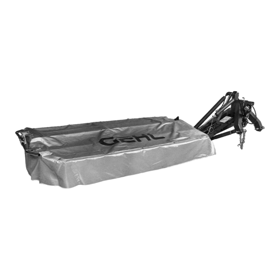
Disc Mower
OPERATOR'S MANUAL
Table of
Contents
Previous
Page
Next
Page
1
2
3
4
5
Advertisement
Table of Contents
Need help?
Do you have a question about the 1162 and is the answer not in the manual?
Ask a question
Questions and answers
Related Manuals for Gehl 1162
Lawn Mower Gehl 1165 Operator's Manual
Disc mower (52 pages)
This manual is also suitable for:
1165
Table of Contents
Save PDF
Print
Rename the bookmark
Delete bookmark?
Delete from my manuals?
Login
Sign In
OR
Sign in with Facebook
Sign in with Google
Upload manual
Upload from disk
Upload from URL


Need help?
Do you have a question about the 1162 and is the answer not in the manual?
Questions and answers