Advertisement
Advertisement
Table of Contents

Related Manuals for fitness gear STE00021

Summary of Contents for fitness gear STE00021
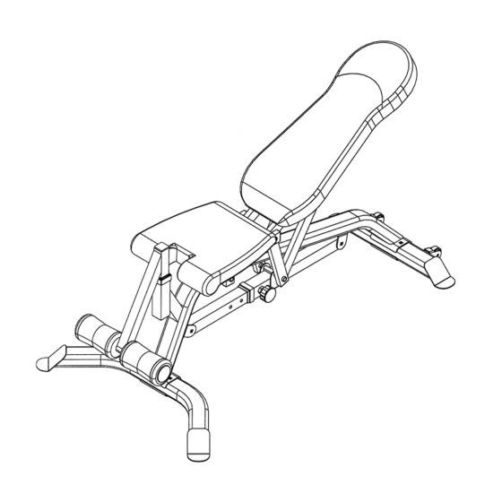
- Page 1 MULTI-PURPOSE BENCH STE00021...
-
Page 2: Table Of Contents
ORDERING PARTS..................BEFORE YOU BEGIN Thank you for selecting the FITNESS GEAR Multi Purpose Bench, STE00021. For your safety and benefit, read this manual carefully before using the machine. As a manufacturer, we are committed to provide you complete customer satisfaction. If you have any questions, or find there are missing or damaged parts, we guarantee you complete satisfaction through direct assistance from our factory. - Page 3 WARNING: BEFORE BEGINNING ANY EXERCISE PROGRAM, CONSULT YOUR PHYSICIAN. THIS IS ESPECIALLY IMPORTANT FOR INDIVIDUALS OVER THE AGE OF 35 OR PERSONS WITH PRE-EXISTING HEALTH PROBLEMS. READ ALL INSTRUCTIONS BEFORE USING ANY FITNESS EQUIPMENT. DICK’S SPORTING GOODS ASSUMES NO RESPONSIBILITY FOR PERSONAL INJURY OR PROPERTY DAMAGE SUSTAINED BY OR THROUGH THE USE OF THIS PRODUCT.
-
Page 4: Hardware Pack
HARDWARE PACK... -
Page 5: Assembly Instructions
ASSEMBLY INSTRUCTIONS Tools Required Assembling the Machine: Two Adjustable Wrenches and Allen Wrenches. NOTE: It is strongly recommended this machine be assembled by two or more people to avoid possible injury. STEP 1 (See Diagram 1) A.) Attach the Main Frame (#1) to the Front Stabilizer (#3). Secure it with two M10 x 2 ¾” Carriage Bolts (#20), one Bracket (#11), two ∅... -
Page 6: Incline Adjustment Bar
STEP 2 (See Diagram 2) A.) Slide the Sliding Block (#5) onto the Incline Adjustment Bar (#4). B.) Attach both ends of Incline Adjustment Bar to the open brackets on the Main Frame (#1). Secure each end with one M10 x 2 ½” Carriage Bolt (#21), Ø ¾” Washer (#26), and M10 Aircraft Nut (#27). -
Page 7: Seat Support Frame
STEP 3 (See Diagram 3) A.) Attach the lower holes on the Backrest Supports (#7) to the pivot on the Sliding Block (#5). Secure them with one M12 x 6 ½” Allen Bolt (#18), two ∅ 1” Washers (#254), and one M12 Aircraft Nut (#25). -
Page 8: Backrest Board
STEP 4 (See Diagram 4) J.) Insert the Foam Tube Assembly (#10) into the opening on the Main Frame (#1). Thread the T-shaped Lock Pin (#32) into the selected hole to lock the Foam Tube Assembly at desired height. K.) Insert the Foam Tube (#34) halfway through the hole on the Foam Tube Assembly. -
Page 9: Exploded Diagram
EXPLODED DIAGRAM... -
Page 10: Parts List
PARTS LIST KEY NO. DESCRIPTION Q’ty Main Frame Rear Stabilizer Front Stabilizer Incline Adjustment Bar Sliding Block Seat Support Frame Backrest Support Seat Backrest Board Foam Tube Assembly Bracket Foam Roll End Cap Foam Roll Sliding Block Sleeve Lock Knob 1 5/8”... -
Page 11: Limited Warranty
LIMITED WARRANTY Dick's Sporting Goods, Inc. (the "Company") warrants this product to be free from defects in workmanship and materials as follows: Who is Covered This Limited Warranty covers only the person who first bought the product. This Limited Warranty is not transferable to anyone else.
Need help?
Do you have a question about the STE00021 and is the answer not in the manual?
Questions and answers