Table of Contents
Advertisement
Quick Links
Attention! Reliability and life of the product are provided not only by the quality of product itself,
and also by the compliance with operating modes and conditions, therefore, meeting the
requirements of this document is mandatory.
Lun-9C Fire and Intrusion Alarm Communicator
ORTUS Group
Operation Manual
Control Panel
2016
GSM Control Panel
Configuration Software
Central Monitoring Station
Product Compatibility Table
(Orlan-M11-based)
Lun-9C
Version
Configurator
Version
Orlan
Version
Advertisement
Table of Contents

Summary of Contents for Ortus Lun-9C
-
Page 1: Operation Manual
Attention! Reliability and life of the product are provided not only by the quality of product itself, and also by the compliance with operating modes and conditions, therefore, meeting the requirements of this document is mandatory. Lun-9C Fire and Intrusion Alarm Communicator Operation Manual Product Compatibility Table... -
Page 2: Table Of Contents
Table of contents 1. Purpose.....................................3 2. Safety Precautions.................................3 3. Technical characteristics.............................3 4. Appearance and functions of unit terminals......................4 5. Operation peculiarities..............................5 5.1. Unit operation modes............................6 5.2. Control Panels connected..........................7 5.3. LED indicators..............................7 6. Installation and connection............................8 6.1. Installation preparation............................8 6.2. Unit installation..............................8 6.3. -
Page 3: Purpose
Attention! The unit has no open live parts posing the electrical shock hazard. 3. Technical characteristics Lun-9C Control Panel has the following technical characteristics (Table 1): Table 1. Basic technical parameters of Lun-9C Parameter name... -
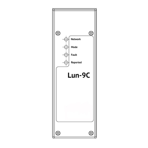
Page 4: Appearance And Functions Of Unit Terminals
4. Appearance and functions of unit terminals The appearance of the unit is shown in Figure 1, the appearance of the board is shown in Figure 2. Figure 1. Unit appearance АДМА.425938.003 РЭ Rev. en_11... -
Page 5: Operation Peculiarities
Z3** Input 3 (fire indication test) OUT*** Input for transmission of Lun-9C malfunction warning to the Control Panel Power supply input +(10…14)V Common contact ( – ) * Communication protocols: tone Contact ID; pulse with the speed of 20 bit/sec ** Terminal resistors of 4.7 kOhm are used, see the connection diagrams in Figures 3, 4. -
Page 6: Unit Operation Modes
In case the Control Panel's output for peripheral devices cannot provide the maximum load current of 0.7A (required for the normal operation of the Lun-9C board), it is recommended to connect the board power supply terminals to the external 12V battery with the own charger. -
Page 7: Control Panels Connected
5.2. Control Panels connected To provide the unit operation in the mode No. 1, Control Panels that comply with EN 54-21 and have malfunction message input can be connected. To provide the unit operation in the mode No. 2, any Control Panels with a communicator for message transmission via telephone lines and supporting ContactID protocol in DTMF mode or in the pulse mode with the passing speed of 20bps can be connected. -
Page 8: Installation And Connection
Figure 1 – over the corresponding hole on the unit housing; ● Configure the Control Panel according to the manufacturer’s instruction (see section 6.3); ● Configure Lun-9C unit (see section 6.4). 6.2. Unit installation The unit shall be installed as follows: 1. -
Page 9: Unit Configuration Recommendations
The detailed description of configuring can be found in the instructions to Configurator program. The instructions are delivered on “Phoenix-4” installation disk and they are also available at www.ortus.io. 7. Remote control arrangements CMS remote control can be established using “Phoenix-4” software (see “Phoenix-4”... -
Page 10: Appendix 1. Connection Diagrams
13. Appendix 1. Connection diagrams Attention! Adherence to these connection diagram is mandatory. Failure to comply with this requirement can lead to the unit malfunction and warranty disclaimer. Figure 3. Diagram of connection of the unit to the Control Panel. Option 1 Figure 4. - Page 11 When using the unit together with “Strelets” Control Panel, you should install MC-1 module to the Lun-9C PCB (for the voltage level matching). This module is placed to XP2 connector (see Figure 5). Then you connect “Strelets: Control Panel to the unit (see Figure 6).
-
Page 12: Appendix 2. Warranty Service Regulations
● damages caused by intrusion of foreign items, materials, liquids, insects, etc. inside the Equipment; ● equipment with external defects (obvious mechanical damages, cracks, chips on the housing and inside the device, broken antenna or connector pins). Manufacturer: ORTUS Group 5624 California st, San Francisco, CA 94121, USA Tel.:+1 650 240 27 62 mail: info@ortus.io...
Need help?
Do you have a question about the Lun-9C and is the answer not in the manual?
Questions and answers