Table of Contents
Advertisement
For certified companies
ROTEX Solaris
Solar system
Control unit for large-scale installations RPS3 25M
Operating and installation manual
Valid for the following components
ROTEX SolarisRPS3 25M
Solaris R3 temperature difference controller
Sanicube Solaris and HybridCube storage tank
Serial number
Customer
GB
Issue 03/2010
Advertisement
Table of Contents

Subscribe to Our Youtube Channel
Related Manuals for Rotex Solaris RPS3 25M

Summary of Contents for Rotex Solaris RPS3 25M
- Page 1 For certified companies ROTEX Solaris Solar system Control unit for large-scale installations RPS3 25M Operating and installation manual Valid for the following components Issue 03/2010 ROTEX SolarisRPS3 25M Solaris R3 temperature difference controller Sanicube Solaris and HybridCube storage tank Serial number Customer...
- Page 2 All ongoing costs, in particular claims for damages, are excluded. There is no guarantee claim for wear parts (according to the ROTEX definition), such as lights, switches, fuses. The warranty claim is automatically void if the connecting pipes are not run with continuous gradients and the lower edges of the collectors are not installed with a constant slope (at least 2 %) towards the return connection in the case of opposite side connections or installed horizontally in the case of same-side connections.
-
Page 3: Table Of Contents
Burner inhibit contact ................38 FA ROTEX Solaris RPS3 25M - 03/2010... - Page 4 Notes ................. . . 59 FA ROTEX Solaris RPS3 25M - 03/2010...
-
Page 5: Safety
Relevant documents The documents listed below are part of the technical documentation for the ROTEX Solaris system and must also be observed. The documents are included in the scope of supply of the individual components. -
Page 6: Avoiding Danger
ROTEX Solaris systems are state-of-the-art and are built to meet all recognised technical requirements. However, improper use may result in serious physical injuries or death, as well as property damage. To avoid danger ROTEX Solaris systems should only be installed and operated: –... -
Page 7: Product Description
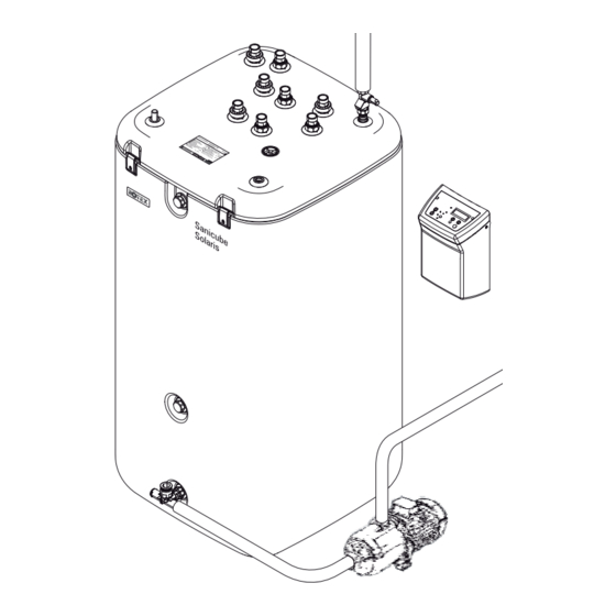
Equalising pipe PS1 Solar circulation pump (on-site) Return flow connection pipe PS2 Solar booster pump (on-site, optional) Illustration 2-1 Standard design of a ROTEX Solaris system (double-sided connection is recommended by ROTEX) FA ROTEX Solaris RPS3 25M - 03/2010... -
Page 8: Brief Description
Product description Brief description The ROTEX Control unit RPS3 25M is used to control a circulation pump installed on-site and if required also a booster pump in a Solaris large-scale system (thermal solar system for hot water generation and heating support). -
Page 9: System Components
ROTEX Solaris R3 controller with storage tank temperature sensor, return flow temperature sensor, terminal connector for collector temperature sensor, terminal block for mains and pump connection Solaris documentation Illustration 2-2 Control unit RPS3 25M FA ROTEX Solaris RPS3 25M - 03/2010... -
Page 10: Flow Rate Meter And Regulating Valve
Consists of: – Connecting T-piece (a). – Connection pipe with ball valve and connection fitting to Ø 28 mm pipe diameter (b). – Blanking plug with clamp (c). Illustration 2-6 CON RA 25M (optional) FA ROTEX Solaris RPS3 25M - 03/2010... - Page 11 Equalising pipe for preventing differences in level between connected hot water storage tanks in a row of storage tanks. Consists of: – Equalising pipe. Use with CON SXE and CON RA 25M. Illustration 2-11 AGLE (optional) FA ROTEX Solaris RPS3 25M - 03/2010...
-
Page 12: Installation
Careful design of the system is required to ensure that the circulation pump and the connection pipes are adequately dimensioned (see section 3.2). In the case of large-scale systems, the hydraulic resistance of the plastic connection pipes available from ROTEX is usually too high. We recommend that you install connection lines made from rigid copper pipes on-site. -
Page 13: System Design
The diagram shows the pressure drop in a row of solar panels including the connection fittings, with and without the influence of the connection pipes from connection set CON X20 25M. The influence of the plastic connection pipes available from ROTEX depending on the required length can be calculated precisely with the help of Image 8-6 in chapter 8.3. -
Page 14: Preparatory Installation Work
Install the collector temperature sensor on the last solar panel before the common feed line (see installation manual for the Solaris solar panels). • ROTEX Set up the hot water storage tanks and heat generators (see the installation and operating manuals provided). Control unit RPS3 25M WARNING! Live parts can cause an electric shock on contact and cause life-threatening burns and injuries. - Page 15 7. Attach the housing baseplate to the hot water storage tank using the 2 screws from the handle (A) at the top and the plastic rawlplug and screw provided at the bottom. FA ROTEX Solaris RPS3 25M - 03/2010...
-
Page 16: Hydraulic Connection
When connecting several hot water storage tanks, fit the end of the connection line to the connecting T-piece mounted on the extension hot water storage tank. One CON RA 25M is required per tank (see also section 3.9). Illustration 3-13 Step 2 Illustration 3-14 Step 3 FA ROTEX Solaris RPS3 25M - 03/2010... -
Page 17: Flowguard, Flowsensor (Optional)
It can be used to set the flow distribution over several storage tanks and the total flow rate through the collector array. The display range is 2...16 l/min. Illustration 3-16 FlowGuard FLG accessory FA ROTEX Solaris RPS3 25M - 03/2010... - Page 18 6. Plug the FlowSensor cable (f) into the FlowSensor (c) and into the FLS position (4-pin, see Image 3-24) on the edge of the Solaris R3 controller PCB. Illustration 3-19 Installation of FlowSensor FLS FA ROTEX Solaris RPS3 25M - 03/2010...
-
Page 19: Temperature Sensor
3. Position the storage tank sensor at a depth of approx. 70 cm in the probe tube (use a cable tie). Illustration 3-20 Step 1 Illustration 3-21 Steps 2+3 Illustration 3-22 Steps 2+3 4. Push the sealing plug into the well, and run the cables. Illustration 3-23 Step 4 FA ROTEX Solaris RPS3 25M - 03/2010... -
Page 20: Electrical Connection
5. Place controller into the housing baseplate from above. • Make sure that the loops in the cable are pointing downwards (as shown in Image 3-27 to Image 3-28). FA ROTEX Solaris RPS3 25M - 03/2010... - Page 21 – Multiwire with cable end sleeve without insulation collar 2.5 mm Illustration 3-29 Connecting the wiring to the terminal block Illustration 3-30 Terminal assignment on the terminal block of the control unit RPS3 25M (for key, see chapter 8.4, Image 8-9) FA ROTEX Solaris RPS3 25M - 03/2010...
-
Page 22: Connecting Severaldhw Storage Tanks Together
To ensure an appropriate storage tank volume on large-scale Solaris systems, it is necessary to connect several hot water storage tanks in parallel. It is possible to connect a maximum of 3 hot water storage tanks to form a storage battery with the ROTEX tank extension kits. With the Solaris CON SX ( 16 01 07) tank extension kit, 2 hot water storage tanks which can be used with Solaris systems can be connected (Image 3-32). - Page 23 Solaris return line FlowSensor Solaris flow line FlowGuard ∆ Difference in level in non-pressurised storage tank area Equalising pipe AGLE Equalising pipe extension kit Illustration 3-32 Operating principle of the common return flow pipe FA ROTEX Solaris RPS3 25M - 03/2010...
- Page 24 If the Solaris system is to be connected to a hot water storage tank which is already in operation, the non-pressurised storage tank zone must first be drained. 1. Unscrew the caps of the Solaris return connections (see chapter 2.1, Image 2-1, Pos. 17) from the hot water storage tanks. FA ROTEX Solaris RPS3 25M - 03/2010...
- Page 25 Solaris flow manifold CON SXE (B) flow manifold from storage tank extension kit 2 Connecting T-piece FlowSensor FlowGuard Illustration 3-34 Installing the flow manifold from storage tank extension kits CON SX and CON SXE FA ROTEX Solaris RPS3 25M - 03/2010...
-
Page 26: Commissioning And Decommissioning
5 °C in the solar circuit can be guaranteed (e. g. by previous heating of the DHW storage tank). ROTEX recommends not operating the installation in extremely frosty conditions. All the following work must be carried out in the specified sequence. - Page 27 12. Install heat insulation at the connection points of the pipelines. 13. Instruct the user, fill out the acceptance report, and send it to the address indicated on the rear cover of this manual. FA ROTEX Solaris RPS3 25M - 03/2010...
-
Page 28: Decommissioning
(e. g. draining). If there is a danger of frost for only a few days, the excellent heat insulation means that the ROTEX Solaris hot water storage tank does not have to be drained, provided that the storage tank temperature is monitored regu- larly and does not fall below +3 °C. -
Page 29: Control Unit
These functions are separately identified by symbols. Software updates to the Solaris R3 controller may only be carried out by the ROTEX service technician. The mains switch disconnects the Solaris R3 controller completely from the mains supply. Operating the mains switch requires greater pressure than actuating the operating buttons does. -
Page 30: Pump Operation
A heating technician can change the booster temperature by means of the "T max" parameter. As soon as the collector temper- ature drops more than 5 K below “TK max”, pump P2 is switched off automatically again. FA ROTEX Solaris RPS3 25M - 03/2010... -
Page 31: Switch-On Inhibit Functions
Manual operation is toggled on/off by pressing both arrow keys simultaneously (>1 s). CAUTION! Uncontrolled manual operation can result in heat loss, excessively high storage tanks temperatures, and even frost damage in extremely cold situations. FA ROTEX Solaris RPS3 25M - 03/2010... -
Page 32: Solaris Flowsensor
Reset occurs with the following: • Via menu path: activation by the heating engineer in the "System" setup menu. • Rapid access: simultaneously press the OK and the arrow keys. FA ROTEX Solaris RPS3 25M - 03/2010... -
Page 33: Frost Protectionfunction
Flow rate 0.0 to 40.0 l/min 0.1 l/min voltage output 0.36 to 3.5 V FlowSensor FLS100 with voltage output 0.0 to 100.0 l/min 0.36 to 3.5 V Table 5-2 Overview of measurement points FA ROTEX Solaris RPS3 25M - 03/2010... -
Page 34: Display During Start-Up
– When the operating display appears, the self test is complete. – For safety reasons, the functions of the pumps and their operating condition lamps can only be tested manually (see section 5.2.5). FA ROTEX Solaris RPS3 25M - 03/2010... -
Page 35: Display During Operation
(see Image 5-5). The control unit starts working with the changed parameter value(s) immediately. The display always returns to the operating display mode after 10 minutes, provided that no key is pressed during this time. FA ROTEX Solaris RPS3 25M - 03/2010... - Page 36 Control unit operation Illustration 5-5 Setup menu FA ROTEX Solaris RPS3 25M - 03/2010...
-
Page 37: Password Protection
(info parameters) are set to zero. When the overall reset function is initiated via the menu path, the total heat yield is preserved. Using the rapid access via the key combination, even this value is deleted. FA ROTEX Solaris RPS3 25M - 03/2010... -
Page 38: Correcting Values For Measurement Points
Minimum temperature for burner stop Active Burner inhibit contact VBSK Delay for burner inhibit contact Time Storage tank temperature Illustration 5-6 Example: Function of the delay time when activating the burner inhibit contact FA ROTEX Solaris RPS3 25M - 03/2010... -
Page 39: Recommended Settings
Table 5-5 Overview of parameters During commissioning, the system parameters must be adjusted individually to suit the installed system, and might need fine tuning during subsequent operation. Usually, the system will operate with the default settings. FA ROTEX Solaris RPS3 25M - 03/2010... -
Page 40: Other Adjustments Of Your Solaris System
10 to 15 K. During operation with circulation pump P1, for example at a return temperature of 50 °C, set a solar panel temperature of approximately 60 to 65 °C. If a FlowSensor (FLS) or heat meter is installed on-site, the flow volume can be set by direct measurement during operation with the pump. FA ROTEX Solaris RPS3 25M - 03/2010... -
Page 41: Recommended Settings For Auxiliary Heating Via External Heat Sources Or The Electric Heater, Burner Inhibit Contact
In this way, the storage capacity is used in an optimal manner with a minimum charging temperature; an adequate amount of hot water is available. FA ROTEX Solaris RPS3 25M - 03/2010... -
Page 42: Domestic Water Hygiene
(legionella protection), the stored water should be heated once to over 60 °C or that the stored hot water should be drained (see technical data in the storage tank manual). FA ROTEX Solaris RPS3 25M - 03/2010... -
Page 43: Faults And Malfunctions
"Yes", all events will be deleted. Deletion of individual events is not possible. An overview of the possible entries in the incidence memory can be found in Table 6 -1. FA ROTEX Solaris RPS3 25M - 03/2010... -
Page 44: Troubleshooting
Comply with the relevant safety at work regulations. CAUTION! Danger of burning on hot surfaces. • Let the unit cool down for a sufficiently long time before maintenance and inspection work. • Wear protective gloves. FA ROTEX Solaris RPS3 25M - 03/2010... - Page 45 If steam escapes continuously from the Solaris DHW storage tank during solar radiation, the flow rate is too low. • In this case, the system settings must be checked. Special notes on electric sensors Only original ROTEX replacement parts may be used. • Evaluate the display of the Solaris R3 control unit. •...
-
Page 46: Hydraulic System Integration
15 60 16) CAUTION! ROTEX units can optionally be fitted with plastic non-return valves ( 16 50 70). These are suitable for operating temperatures up to 95 °C. If a heat exchanger is to be operated above 95 °C, the customer must install a different non-return valve. - Page 47 Hydraulic system integration Illustration 7-2 Standard Solaris integration with GasSolarUnit (GSU) Illustration 7-3 Standard Solaris integration with air-water heat pump (HPSU Bi-Bloc with room heating and cooling function) FA ROTEX Solaris RPS3 25M - 03/2010...
- Page 48 Hydraulic system integration Illustration 7-4 Solaris integration when using several Solaris storage tanks (SCS) (large-scale installations) FA ROTEX Solaris RPS3 25M - 03/2010...
- Page 49 Hydraulic system integration Illustration 7-5 Solaris integration with GSU cascade systems FA ROTEX Solaris RPS3 25M - 03/2010...
- Page 50 Illustration 7-6 Example diagram showing Solaris integration in a large-scale installation with 8000 l storage volume (with 16 HYC hot water storage tanks) Suitable for up to 156 m collector area (60 solar panels) 1) The system schematics shown make no claims to completeness and are no replacement for careful system planning. FA ROTEX Solaris RPS3 25M - 03/2010...
-
Page 51: Short Designations
Storage tank charging pump (only if there are several hot water storage tanks on site in a linked system) Circulation pump Circulation pump on site Booster pump RPS3 25M Control unit Solaris Accessories 16 41 11-44 Return temperature limiter on site FA ROTEX Solaris RPS3 25M - 03/2010... -
Page 52: Connection Of A Pressurised Collector System
ROTEX Solaris system (DrainBack) and thus the Control unit RPS3 25M cannot be used. Instead, the heating installation can be implemented with the ROTEX Solaris pressurised system. The following Solaris compo- nents can be used equally in both systems: •... -
Page 53: Technical Data For
0.67 0.99 1.30 1.62 1.93 2.24 2.56 2.87 3.19 3.50 Table 8 -2 Table of the Solaris sensors Sensor resistance (PTC, Pt 1000) t Temperature Illustration 8-1 Resistance characteristics of the Solaris sensors FA ROTEX Solaris RPS3 25M - 03/2010... -
Page 54: Hydraulic Resistance
Sensor output voltage Illustration 8-2 Characteristics of the FlowSensors Technical data for ROTEX condensing boilers, heat pumps and hot water storage tanks can be found in the ROTEX price list and the corresponding technical documentation for the products. Hydraulic resistance... - Page 55 Return connection set with corrugated connecting pipe, ball P Pressure drop valve and push-in connection fitting Ø 28 mm Illustration 8-5 Hydraulic resistance of the return connection on the hot water storage tank FA ROTEX Solaris RPS3 25M - 03/2010...
- Page 56 Flow rate in collector circuit ∆ Feed line (ROTEX VA 15 Solar) P Pressure drop Illustration 8-6 Hydraulic resistance in ROTEX plastic connection pipes, per metre ∆ Flow rate in collector circuit P Pressure drop Illustration 8-7 Hydraulic resistance of the scalding protection mixer valve VTA 32...
-
Page 57: Terminal Assignment
Switched phase circulation pump Switched phase Booster pump Circulation pump Optional booster pump Earthing Power Mains supply Storage tank temperature sensor Return flow temperature sensor Collector temperature sensor Illustration 8-9 Terminal assignment, terminal block FA ROTEX Solaris RPS3 25M - 03/2010... -
Page 58: List Of Keywords
FlowSensor ........17 FA ROTEX Solaris RPS3 25M - 03/2010... -
Page 59: Notes
Notes Notes FA ROTEX Solaris RPS3 25M - 03/2010... - Page 60 FA ROTEX Solaris RPS3 25M - 03/2010...
Need help?
Do you have a question about the Solaris RPS3 25M and is the answer not in the manual?
Questions and answers