
Subscribe to Our Youtube Channel
Related Manuals for Cisco 1830 Series


Summary of Contents for Cisco 1830 Series
- Page 1 ETTING TARTED UIDE Cisco Aironet 1830 Series Access Points First Published: October 1, 2015...
- Page 2 About this Guide About the Access Point Safety Instructions Unpacking the AP Ports and Connectors on the AP Preparing the AP for Installation Installation Overview Performing a Pre-Installation Configuration Mounting and Grounding the Access Point Powering the Access Point Configuring and Deploying the Access Point Checking the Access Point LEDs Miscellaneous Usage and Configuration Guidelines Related Documentation...
-
Page 3: About This Guide
This guide provides instructions on how to install and configure your Cisco Aironet 1830 Series Access Point. This guide also provides mounting instructions and limited troubleshooting procedures. The 1830 Series Access Point is referred to as the access point, or abbreviated as AP in this document. About the Access Point The Cisco Aironet 1830 series access point is an 802.11 a/b/g/n/ac (Wave 2) access point, with internal... -
Page 4: Access Point Features
Centralized – • Supports Cisco Mobility Express solution. The 1830 series access point can operate as a master AP (having an integrated wireless controller functionality) in a Cisco Mobility Express network. For more information, see the Cisco Mobility Express User Guide at the following URL: http://www.cisco.com/c/en/us/td/docs/wireless/access_point/mob_exp/1/user_guide/b_ME_User_... - Page 5 3 dBi and 5 dBi in 2.4 GHz and 5 GHz bands respectively. A full listing of the access point's features and specification are provided in the Cisco Aironet 1830 Series Access Point Data Sheet, at the following URL: http://www.cisco.com/c/en/us/products/collateral/wireless/aironet-1830-series-access-points/datashee...
-
Page 6: Safety Instructions
Translated versions of the following safety warnings are provided in the translated safety warnings document that is shipped with your access point. The translated warnings are also in the Translated Safety Warnings for Cisco Aironet Access Points, which is available on Cisco.com. Warning IMPORTANT SAFETY INSTRUCTIONS This warning symbol means danger. - Page 7 Step 2 Step 3 Verify that you have received the items listed below. If any item is missing or damaged, contact your Cisco representative or reseller for instructions. The access point – Mounting bracket (AIR-AP-BRACKET-1= or AIR-AP-BRACKET-2=, only if selected when –...
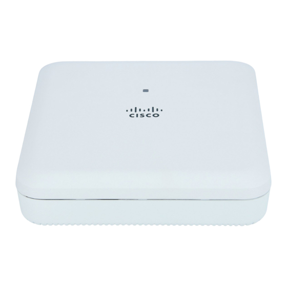
- Page 8 Ports and Connectors on the AP The 1830 series access points have an LED indicator on the face of the unit, above the Cisco logo, as shown in Figure 1. For information on the LED scheme, see the “Access Point Status LEDs” section...
- Page 9 Figure 2 Access Point Ports and Connections Security hasp for padlocking AP to mounting USB 2.0 port bracket (No software support at this time) Mode button PoE-In port (Ethernet Uplink port) For information on how to use the Mode button, see “Using the Mode Button”...
-
Page 10: Table Of Contents
Cisco recommends that you make a site map showing access point locations so that you can record the device MAC addresses from each location and return them to the person who is planning or managing your wireless network. -
Page 11: Performing A Pre-Installation Configuration
Performing a Pre-Installation Configuration For a Cisco Mobility Express deployment, see the Cisco Mobility Express User Guide at this URL: http://www.cisco.com/c/en/us/td/docs/wireless/access_point/mob_exp/1/user_guide/b_ME_User_Guid e.html The following procedures ensure that your access point installation and initial operation go as expected. This procedure is optional. -
Page 12: Step 1
Controller Configuration Guide for the release you are using, for additional information. c. Set the Cisco wireless LAN controller as the master so that new access points always join with d. Make sure DHCP is enabled on the network. The access point must receive its IP address through DHCP. - Page 13 Note unable to find the Master Cisco wireless LAN controller. Check the connection between the access point and the Cisco wireless LAN controller and be sure that they are on the same subnet. b. If the access point shuts down, check the power source.
- Page 14 When you are installing a Layer 3 access point on a different subnet than the Cisco Note wireless LAN controller, be sure that a DHCP server is reachable from the subnet on which you will be installing the access point, and that the subnet has a route back to the Cisco wireless LAN controller.
-
Page 15: Mounting And Grounding The Access Point
Mounting and Grounding the Access Point Cisco Aironet 1832 series access points can be mounted in several configurations – on a suspended ceiling, on a hard ceiling or wall, on an electrical or network box, and above a suspended ceiling. -
Page 16: Powering The Access Point
The AP can be powered using: • 48 V DC power via the 48VDC port, using Cisco Power Adapter AC DC AIR-PWR-C=. Ensure that the power cable is routed through the strain relief retention clips cast into the enclosure. See Figure •... - Page 17 Figure 4 Routing the DC Power Cable Kensington lock slot DC power cable plugged into the 48VDC port Power cable routed through the strain relief AP secured using a padlock retention clips DC power cable...
-
Page 18: Configuring And Deploying The Access Point
This section describes how to connect the access point to a wireless LAN controller. The configuration process takes place on the controller. See the Cisco Wireless LAN Controller Configuration Guide for additional information. For a Cisco Mobility Express deployment, see the Cisco Mobility Express User Guide at the following URL: http://www.cisco.com/c/en/us/td/docs/wireless/access_point/mob_exp/1/user_guide/b_ME_User_Guid e.html... - Page 19 • DHCP server discovery—This feature uses DHCP option 43 to provide controller IP addresses to the access points. Cisco switches support a DHCP server option that is typically used for this capability. For more information about DHCP option 43, see the “Configuring DHCP Option 43”...
-
Page 20: Deploying The Access Point On The Wireless Network
Cisco wireless LAN controller. Also, if the access point is not on the same subnet as the Cisco wireless LAN controller, be sure that there is a properly configured DHCP server on the same subnet as the access point. See the “Configuring DHCP Option 43”... - Page 21 Checking the Access Point LEDs Access Point Status LEDs The location of the access point status LED is shown in Figure Regarding LED status colors, it is expected that there will be small variations in color intensity Note and hue from unit to unit. This is within the normal range of the LED manufacturer’s specifications and is not a defect.
- Page 22 Table 2 LED Status Indications (continued) Message LED State Message Type Meaning Operating status Blinking amber Software upgrade in progress Cycling through green, Discovery/join process in progress red, and amber Rapidly cycling Access point location command invoked from through red, green, controller web interface.
-
Page 23: Using The Mode Button
Miscellaneous Usage and Configuration Guidelines Using the Mode Button Using the Mode button (see Figure 2) you can: • Reset the AP to it’s default factory-shipped configuration. • Clear the AP’s internal storage, including all configuration files and the regulatory domain configuration. - Page 24 2500 series controllers and the Controller Network Module within the Cisco 28/37/38xx Series Integrated Services Routers. The maximum number of access points varies for the Cisco WiSM2, depending on which Note controller software release is being used.
- Page 25 Important Information for Controller-based Deployments Keep these guidelines in mind when you use 1832 series access points: • The access point can only communicate with Cisco wireless LAN controllers. • The access point does not support Wireless Domain Services (WDS) and cannot communicate with WDS devices.
- Page 26 The 1830 series access point uses the type-length-value (TLV) format for DHCP Option 43. DHCP servers must be programmed to return the option based on the access point’s DHCP Vendor Class Identifier (VCI) string (DHCP Option 43). The VCI string for the 1830 series access point is: Cisco AP c1830 The format of the TLV block is listed below: •...
-
Page 27: Related Documentation
10.126.126.2 and 10.127.127.2. The type is f1(hex). The length is 2 * 4 = 8 = 08 (hex). The IP addresses translate to 0a7e7e02 and 0a7f7f02. Assembling the string then yields f1080a7e7e020a7f7f02. The resulting Cisco IOS command added to the DHCP scope is option 43 hex f1080a7e7e020a7f7f02. -
Page 28: Declarations Of Conformity And Regulatory Information
Declarations of Conformity and Regulatory Information This section provides declarations of conformity and regulatory information for the Cisco Aironet 1830 Series Access Points. You can find additional information at this URL: www.cisco.com/go/aironet/compliance Manufacturers Federal Communication Commission Declaration of Conformity Statement... -
Page 29: Vcci Statement For Japan
The Part 15 radio device operates on a non-interference basis with other devices operating Caution at this frequency when using the integrated antennas. Any changes or modification to the product not expressly approved by Cisco could void the user’s authority to operate this device. VCCI Statement for Japan... -
Page 30: Guidelines For Operating Cisco Aironet Access Points In Japan
Guidelines for Operating Cisco Aironet Access Points in Japan This section provides guidelines for avoiding interference when operating Cisco Aironet access points in Japan. These guidelines are provided in both Japanese and English. Japanese Translation 03-6434-6500 English Translation This equipment operates in the same frequency bandwidth as industrial, scientific, and medical devices such as microwave ovens and mobile object identification (RF-ID) systems (licensed premises radio stations and unlicensed specified low-power radio stations) used in factory production lines. - Page 31 Material Safety Law prohibits the use of UL-certified cables (that have the “UL” shown on the code) for any other electrical devices than products designated by CISCO. The use of cables that are certified by Electrical Appliance and Material Safety Law (that have “PSE” shown on the code) is not limited...
-
Page 32: Industry Canada
Industry Canada Access Point Models Certification Number AIR-AP1832I-A-K9 2461B-102095 AIR-AP1832I-A-K9C AIR-AP1832I-UXK9 AIR-AP1832I-UXK9C Canadian Compliance Statement This device complies with Industry Canada licence-exempt RSS standard(s). Operation is subject to the following two conditions: (1) this device may not cause interference, and (2) this device must accept any interference, including interference that may cause undesired operation of the device. - Page 33 d'antenne énumérés ci-dessous et ayant un gain admissible maximal et l'impédance requise pour chaque type d'antenne. Les types d'antenne non inclus dans cette liste, ou dont le gain est supérieur au gain maximal indiqué, sont strictement interdits pour l'exploitation de l'émetteur. Antenna Type Antenna Gain Antenna Impedance...
- Page 34 Declaration of Conformity with regard to the R&TTE Directive 1999/5/EC & Medical Directive 93/42/EEC...
- Page 35 The following standards were applied: EMC—EN 301.489-1 v1.9.2; EN 301.489-17 v2.2.1 Health & Safety—EN60950-1: 2006; EN 50385: 2002 Radio—EN 300 328 v 1.8.1; EN 301.893 v 1.7.1 The conformity assessment procedure referred to in Article 10.4 and Annex III of Directive 1999/5/EC has been followed.
-
Page 36: Declaration Of Conformity For Rf Exposure
This Device Meets International Guidelines for Exposure to Radio Waves The 1830 series device includes a radio transmitter and receiver. It is designed not to exceed the limits for exposure to radio waves (radio frequency electromagnetic fields) recommended by international guidelines. - Page 37 This Device Meets FCC Guidelines for Exposure to Radio Waves The 1830 series device includes a radio transmitter and receiver. It is designed not to exceed the limits for exposure to radio waves (radio frequency electromagnetic fields) as referenced in FCC Part 1.1310.
- Page 38 This Device Meets the Industry Canada Guidelines for Exposure to Radio Waves The 1830 series device includes a radio transmitter and receiver. It is designed not to exceed the limits for exposure to radio waves (radio frequency electromagnetic fields) as referenced in Health Canada Safety Code 6.
-
Page 39: Administrative Rules For Cisco Aironet Access Points In Taiwan
Additional Information on RF Exposure You can find additional information on the subject at the following links: • Cisco Systems Spread Spectrum Radios and RF Safety white paper at this URL: http://www.cisco.com/warp/public/cc/pd/witc/ao340ap/prodlit/rfhr_wi.htm • FCC Bulletin 56: Questions and Answers about Biological Effects and Potential Hazards of Radio Frequency Electromagnetic Fields •... - Page 40 Chinese Translation...
-
Page 41: Chinese Translation
English Translation Administrative Rules for Low-power Radio-Frequency Devices Article 12 For those low-power radio-frequency devices that have already received a type-approval, companies, business units or users should not change its frequencies, increase its power or change its original features and functions. Article 14 The operation of the low-power radio-frequency devices is subject to the conditions that no harmful interference is caused to aviation safety and authorized radio station;... -
Page 42: Portuguese Translation
English Translation Low-power Radio-frequency Devices Technical Specifications Unlicensed National Information Infrastructure 4.7.5 Within the 5.25-5.35 GHz band, U-NII devices will be restricted to indoor operations to reduce any potential for harmful interference to co-channel MSS operations. 4.7.6 The U-NII devices shall accept any interference from legal communications and shall not interfere the legal communications. - Page 43 © 2015 Cisco Systems, Inc. All rights reserved. Cisco and the Cisco logo are trademarks or registered trademarks of Cisco and/or its affiliates in the U.S. and other countries. To view a list of Cisco trademarks, go to this URL: www.cisco.com/go/trademarks. Third-party trademarks mentioned are the property of their respective owners. The use of the word partner does...
- Page 44 Cisco Website at www.cisco.com/go/offices. Cisco and the Cisco logo are trademarks or registered trademarks of Cisco and/or its affiliates in the U.S. and other countries. To view a list of Cisco trademarks, go to this URL: www.cisco.com/go/trademarks. Third-party trademarks mentioned are the property of their respective owners.
Need help?
Do you have a question about the 1830 Series and is the answer not in the manual?
Questions and answers