Table of Contents
Advertisement
High Definition Digital Video Recorder
User's Manual
Installation Manual
Thank you for using our High Definition SD Card Video Recorder. This manual is applicable for HDVR004 &
HDVR004GW. Please read this User's Manual carefully to ensure that you can use the device correctly and safely.
The contents of this manual are subject to be changed without notice.
1 -
Advertisement
Table of Contents

Summary of Contents for Easy Storage HDVR004
-
Page 1: Installation Manual
User’s Manual Installation Manual Thank you for using our High Definition SD Card Video Recorder. This manual is applicable for HDVR004 & HDVR004GW. Please read this User’s Manual carefully to ensure that you can use the device correctly and safely. - Page 2 Warning This device is NOT of waterproof; to prevent it from any accident of fire or electric shock, please do NOT put any container with water on the device or nearby. Do not expose the device to moisture, or extreme temperatures. CAUTION RISK OF ELECTRIC SHOCK DO NOT OPEN...
-
Page 3: Table Of Contents
TABLE OF CONTENTS 1. GENERAL INTRODUCTION ..................4 2. PRODUCT FIGURES ....................6 2.1 F .................................. 6 RONT ANEL 2.2 R ..................................7 EAR PANEL 3. INITIAL SET UP ..................... 8 3.1 T ............................8 AMPER PROOF OUNTING 3.2 P ................................ -
Page 4: General Introduction
1. GENERAL INTRODUCTION The HDVR series mobile digital video recorder is a compact, full-featured H.264 1080p/720p recording system that uses a SD card as a storage device. The recorder unit and associated accessories are specifically designed for operation in a mobile environment. The HDVR system, used in conjunction with the cameras, records up to four channels of full-motion video and audio data to a Class 10 (minimum) SD card. -
Page 5: Power Management
Power Management Reliable power management, wide voltage: +8V~+32VDC; The power input is protected against short positive transient (1500 watts peak pulse power capability with a 10x1000 us waveform); The power input is protected against negative voltage. Applicable for vehicles with +12V or +24V battery. ... -
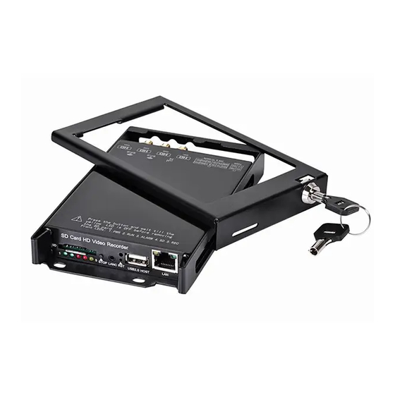
Page 6: Product Figures
2. Product Figures 2.1 Front Panel ①:SD Card Slot ②: Stop Button: For stop recording ③: LANC Port: For connection to an Event button and status indicator ④: Status Lights (1: System; 2: 3G; 3: SD; 4: Alarm; 5: Power; 6: Run) ⑤: USB Host Port: Can be used as a secondary recording device, such as a flash memory card. -
Page 7: Rear Panel
4. ALARM (Red) Status/Description Alarm input when BEEP is set as “ON”. Audible alarm (beep) when enabled. No alarm. 3. SD (Red) Description Reading/Writing data from/to the SD Card. Not Reading/Writing – inactive. 2.2 Rear panel ①: Power, Ground and ACC input. ②: 1x speed sensor, 3x sensors inputs, 1x RS232 port(for GPS) and 1x 5V DC output ③: AV input 1(including audio input 1, video input 1 and power output for camera 1) ④: AV input 2(including audio input 1, video input 1 and power output for camera 2) -
Page 8: Initial Set Up
3. Initial Set Up 3.1 Tamper-proof Case Mounting Use a power drill and screws supplied to fix the bottom cover of the tamper-proof case in the right place inside the vehicle. Put the DVR system inside the bottom cover, and load a SD Card. NOTE: The lock jumper of SD Card should be in OFF position. -
Page 9: Power Connection
3.2 Power Connection 3.2.1. Use Ignition Switch to Turn On/Off DVR System 3.2.2, Turn On / Off DVR System Automatically NOTE The DVR uses DC power input, please be very careful when connecting to the “+” and “-” of the power supply. Wide voltage range of 8V-32V for the DVR. -
Page 10: Camera Connection
3.3 Camera Connection Connect the camera with HDVR. 3.4 Sensor Harness Connection GPS Connection (Option) 10 -... -
Page 11: Event Button And Cable Connection (Option)
3.5 Event Button and Cable Connection (Option) 11 -... -
Page 12: Connect The Hdvr To A Pc With Network
4. Connect the HDVR to a PC with network 4.1 Download and install the VLC player into your computer User will need to install a VLC player to play back the video from HDVR. User can download the VLC player in ftp://ezview.3322.org/DVR/HDVR/vlc-2.0.1-win32.exe. -
Page 13: Basic Operation And Menu System
5. Basic Operation and Menu System 5.1 SD Card Formatting For a brand new SD Card of SDHC standard, it can be used directly. But with situations listed below, you’re required to format it before using: If the SD Card is of SDXC standard (like a 64GB SD Card), the defaulted file format is exFAT, which will not be recognized by the DVR system. -
Page 14: Set Up Recording
5.2 Set up recording Click “Record Details” in the “DVR” menu to set up your recording. 1. Each camera supports up to 1080p30, bitrate varies from 100Kbps to 8000Kbps. Default setting is 1080p30 with bitrate of 3000Kbps. 1200Kbps is recommended for 720p25. DVR uses inteligent bitrate control to save media space when doing H.264 image compression. -
Page 15: Setup Your Cameras
5.3 Setup your cameras Click “Camera Setting” in the DVR menu to setup the cameras. 1. Click CAMx to adjust each camera's brightness, contrast, audio volume, and other settings. 2. Max 12 characters are limited for each camera title. 3. Camera image can be flipped in direction of horizontal or vertical. 4. -
Page 16: Setup Alarms
5.4 Setup alarms Click “Alarm Details” to set up alarm actions. 1. Alarm setting includes 3 external triggers and 1 event button. 2. External triggers can be set with high level active or low level active. 3. Event button can be used to start/stop recording, or trigger an alarm recording. 4. -
Page 17: Setup Power
5.5 Setup Motion Detection Click “Motion Detection” to set up Motion Detection alarm. 1. Up to 12 motion detection areas can be activated for each camera. Each camera needs to be configed individual. 5.6 Setup power Click “Power” in the “Mobile” menu to setup the power supply. 1. -
Page 18: Setup Vehicle Parameters
5.7 Setup vehicle parameters Click “Motor” in the “Mobile” menu to setup vehicle parameters. 1. Speed obtains from GPS (if existing). 2. The item "Speed Limit" is used to set the speed alarm threshold. 3. Combined Recording can be triggered when over speed. 4. -
Page 19: Setup Gps Parameters
5.8 Setup GPS parameters Click “GPS” in the “Mobile” menu to setup the GPS parameters. 1. GPS Status: GPS NOT FOUND: No GPS detected. GPS DATA: GPS is found but data stream error (baudrate or protocol error). GPS GPRMC: GPS GPRMC means correct but inactive GPRMC frames. (GPS searching in processing, or GPS signal is weak or lost) 2. -
Page 20: Setup G-Sensor Parameters
5.9 Setup G-Sensor parameters Click “G-Sensor” in the “Mobile” menu to setup G-Sensor Menu. 1. G-Sensor Instant Value can give the X/Y/Z axis accelerometer values instantly. 2. For Earth gravity effect, it will get about 1.0g on Z axis when DVR is placed on a horizontal platform. 3. -
Page 21: Setup Schedule Record
5.10 Setup schedule record Click “Record Schedule” in the “DVR” menu to setup schedule record. 1. The record schedule allows for 3 time plans per day. 2. Each camera can be scheduled individual, or click "All" to apply the same record schedule to all cameras. 21 -... -
Page 22: Network Setting
5.11 Network setting Click “WiFi network” in the “Network” menu to set up the network. The WiFi of DVR can work in both WiFi AP and WiFi Client mode: AP Mode WiFi AP can be turned ON or Off with checkbox. Local SSID can be renamed, ie. -
Page 23: Set Up 3G Network
5.12 Set up 3G Network Click “3G Network” and “Network Settings”in the “System” menu to setup 3G Network. (3G function is only available with HD DVR for 3G/4G version) 1. 3G Status: 3G NOT FOUND: 3G module is not detected by DVR. 3G LOADED: 3G is loaded without service (SIM card error or no RF signal). -
Page 24: Set Up Date And Time
6. Server Status: When WIFI or 3G/4G is connected with server, it shows “Connected”. When none of WIFI or 3G/4G is found, it shows “Disconnected”. 7. Select suitable Resolution, Bitrate and Framerate for according camera. 8. Use higher Bitrate and Lower Framerate to get better image quality. 9. -
Page 25: Upgrade The Firmware
5.14 Upgrade the firmware Click “Upgrade” in the “System” menu to upgrade the firmware of HDVR or Cameras. System Version includes: DVR Kernel Version DVR App Version MCU FW version Web Menu version Camera FW version Upgrade file should be ended with .tar. After Upgrade completed, web will notice refreshing web page or waiting DVR restart. -
Page 26: Reset The Hdvr
5.15 Reset the HDVR Click “Reset” in the “System” menu to Reset your HDVR. The HDVR can be reset to “Factory Setting” for all setting, or reset to default “WiFi Setting”. You can also reboot the HDVR in this menu. 5.16 User Management Click “User Management”... -
Page 27: Specification
6. Specification Model HDVR004 Operating System Linux 2.6 Start up Time <20 seconds (From power on to recording) Operator Interface English / Simplified Chinese/Russian System Storage SD Card (up to 128GB) H.264 Main/High Profile, HD 1080p30/720p30/540p30 Recording for Video System... -
Page 28: List Of Standard Accessories
GPS Time Synch / NTP (Network Time Protocol) Time Synch via Synchronization time networking Operating Temperature -30 ~ 60°C Relative humidity 5% - 95% Environment Vibration resistance < 3 Grms Resistance to mechanical < 1200 Grms shock Config. FPS per channel allows (1~30fps) ID records vehicle license allows... -
Page 29: Trouble Shooting
8. Trouble Shooting. 1. Q : After connecting the DVR power, no WiFi AP SSID available, 5 and No.6 indicators lights on panel flashing alternately. A: The No.5 and No.6 LED indicator light is “Power” and “Run”. If the 2 indicators lights are flashing alternatively, the DVR missed the ignition signal, please check if the yellow line of the input power lines has connected with the power positive level, or if it’s the same as the setting of the effective electrical level in menu settings. - Page 30 uneven quality and serious counterfeit, customers come to meet this problem usually, the fault disappears after replacing the SD card. 2). USB disk. Because of the cost sensitive reasons, most of USB disks sold on the market are the products of the USB1.1.Their speed can not meet the data rate of the requirements of the DVR. Please replace USB2.0 products for the faster speed.
- Page 31 When the users who need “Power OFF Delay” function, the positive level of the DVR and the ground should be connected directly (through the fuse) to the cathode and anode of the car battery, at the same time attach car ignition signal line to the ACC of the car. Of course, the time of “Power OFF Delay”...
Need help?
Do you have a question about the HDVR004 and is the answer not in the manual?
Questions and answers