
Summary of Contents for Banner Sure Cross DX70
- Page 1 ® Sure Cross DX70 Wireless Point- to-Point Kits Instruction Manual Original Instructions 133214 Rev. L 2 March 2016 133214...
-
Page 2: Table Of Contents
6.3 Certified For Use in the Following Countries ................30 7 Warnings ........................33 7.1 Installing Remote Antennas ...................... 33 7.2 Exporting Sure Cross ® Radios ....................33 7.3 Copyright Notice ........................33 7.4 Banner Engineering Corp. Limited Warranty ................33 7.5 Contact Us ..........................33... -
Page 3: Dx70 Point-To-Point Radios
Outputs: Four sourcing discrete on the Node, eight sourcing discrete on the Gateway Internal antenna models are also available, but are not UL Listed. For more information, contact your local Banner Engineering Corp. representative. WARNING: Not To Be Used for Personnel Protection Never use this device as a sensing device for personnel protection. -
Page 4: Device Components
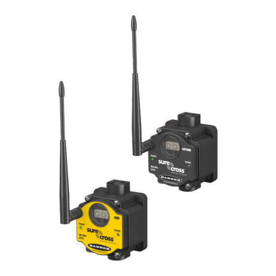
® Sure Cross DX70 Wireless Point-to-Point Kits Replacement DX70 Models Kit Models Device Frequency Replacement DX70 Model Gateway DX70G2X6S4P8 1.1 Device Components 1. Rotary Dials. After the DX70 devices are bound, use the 3. Port, NPT Gland, or Plug. If unused, install the rotary dials on the Gateway to set the Network ID (NID) to provided plug into the 1/2 NPT threaded port. -
Page 5: Setting Up And Installing A Dx70 Point-To-Point Network
® Sure Cross DX70 Wireless Point-to-Point Kits 2 Setting Up and Installing a DX70 Point-to-Point Network To set up and install DX70 kits, follow these steps. These kits ship from the factory bound together and with their inputs and outputs mapped as shown in the I/O mapping tables. 1. -
Page 6: Wiring Your Sure Cross ® Device
Device Use the following wiring diagrams to first wire the sensors and then apply power to the Sure Cross devices. 2.2.1 I/O Mapping All DX70 pairs ship from Banner Engineering with the I/O mapped. 2.2.1 DX70...EM1 Kits Using PNP Inputs Using NPN Inputs −... - Page 7 ® Sure Cross DX70 Wireless Point-to-Point Kits Terminal DX70 Gateway DX70 Node Terminal Label Label Discrete IN 1* ---> Discrete OUT 1 or Lost Link Indicator* Discrete IN 2 ---> Discrete OUT 2 Discrete IN 3 ---> Discrete OUT 3 Discrete IN 4 --->...
-
Page 8: Sensor Connections
® Sure Cross DX70 Wireless Point-to-Point Kits Terminal Label DX70 Gateway DX70 Node Terminal Label Discrete OUT 5 <--- Discrete IN 5 Discrete OUT 6 <--- Discrete IN 6 Discrete OUT 7 <--- Discrete IN 7 Discrete OUT 8 <--- Discrete IN 8 2.2.2 Sensor Connections Refer to the sensor device data sheet for a device specific wiring diagram. -
Page 9: Signal Strength Indicator
Remove Moisture and Condensation. If condensation is present in any device, add a small desiccant packet to the inside of the radio. To help vent the radios, Banner also sells a vented plug (model number BWA-HW-031) for the 1/2-inch NPT port of the SureCross radios. -
Page 10: Other Installation Requirements
For more information about antennas, please refer to the Antenna Basics reference guide, Banner document p/n 132113. This is not a lot of torque and is equivalent to the torque generated without using tools. If a wrench is used, apply only very light pressure. - Page 11 ® Sure Cross DX70 Wireless Point-to-Point Kits Increase the Height of the Antennas Position the external antenna vertically for optimal RF communication. If necessary, consider changing the height of the SureCross radio, or its antenna, to improve reception. For outdoor applications, mounting the antenna on top of a building or pole may help achieve a line-of-sight radio link with the other radios in the network.
-
Page 12: Basic Remote Antenna Installation
I/O Isolation. When connecting analog and discrete I/O to external equipment such as VFDs (Variable Frequency Drives), it may be appropriate to install interposing relays and/or loop isolation devices to protect the DX80 unit from transients, noise, and ground plane interference originating from devices or the environment. Contact Banner Engineering Corp. for more information. - Page 13 ® Sure Cross DX70 Wireless Point-to-Point Kits Weatherproof Remote Antenna Installations Seal the connections with rubber splicing tape and electrical tape to prevent water damage to the cable and connections. Step 1: Verify both connections are clean and dry before connecting the antenna cable to the antenna or other cable.
- Page 14 ® Sure Cross DX70 Wireless Point-to-Point Kits Models Description List Price Antenna, Omni, 900 MHz, 2 dBd, Dome, RP-SMA MALE Box mount, 18-inch BWA-9O2-D antenna cable Antenna, Omni, 2.4 GHz, 2 dBd, Dome, RP-SMA MALE Box mount, 18-inch BWA-2O2-D antenna cable www.bannerengineering.com - Tel: 763.544.3164...
- Page 15 ® Sure Cross DX70 Wireless Point-to-Point Kits Use an N-Type, Pole-Mounted Antenna This antenna mounts remotely from the box, with the SureCross device mounted inside the box. Ground the surge suppressor and antenna. Keep the ground wire as short as possible and make all ground connections to a single-point ground system to ensure no ground loops are created.
- Page 16 ® Sure Cross DX70 Wireless Point-to-Point Kits Models Description List Price BWC-4MNFN15 LMR400 N-Type Male to N-Type Female, 15 m $156 BWC-4MNFN30 LMR400 N-Type Male to N-Type Female, 30 m $296 Model Description Connection List Price Surge Suppressor, Bulkhead, RP-SMA BWC-LMRSFRPB RP-SMA to RP-SMA $111...
-
Page 17: Maintenance
® Sure Cross DX70 Wireless Point-to-Point Kits 3 Maintenance Follow these instructions to perform basic maintenance tasks. 3.1 Replacing the Main Body Gasket Check the main body gasket every time a SureCross device is opened. Replace the gasket when it is damaged, discolored, or showing signs of wear. The gasket must be: •... -
Page 18: Troubleshooting Problems On Your Dx70 Network
RF link fails, all pertinent wired outputs are brought to a predefined state until the link is recovered (default DIP switch setting). Through this process, users of Banner wireless networks can be assured that disruptions in the communications link result in predictable system behavior. -
Page 19: Setting The Network Id On The Dx70S
® Sure Cross DX70 Wireless Point-to-Point Kits 4.2.1 Setting the Network ID on the DX70s The Network ID is a unique identifier assigned to each wireless network that minimizes the chances of two collocated networks interfering with each other. Assigning different NIDs to different networks improves collocation performance in dense installations. -
Page 20: Advanced Setup Instructions And Additional Information
DX70 Wireless Point-to-Point Kits 5 Advanced Setup Instructions and Additional Information Refer to the following sections for advanced setup instructions or additional information on Banner's SureCross wireless technology and its uses. 5.1 Binding the DX70 Gateway and Node DX70 Gateway and Node kits ship from the factory bound to each other. -
Page 21: Specifications
® Sure Cross DX70 Wireless Point-to-Point Kits 5.2 Specifications Radio Range Power 900 MHz, 150 mW: Up to 4.8 km (3 miles) 10 to 30 V dc (Outside the USA: 12 to 24 V dc, ±10%). 2.4 GHz, 65 mW: Up to 3.2 km (2 miles) Consumption: Less than 1.4 W (60 mA) at 24 V dc Radio Transmit Power Housing... -
Page 22: Dx70 Dimensions
® Sure Cross DX70 Wireless Point-to-Point Kits 5.2.1 DX70 Dimensions 65.0 [2.56”] [0.31”] 65.0 80.3 [4.17”] [2.56”] [3.16”] 7.65 1/2” NPT [0.30”] [2.36”] 14.67 [0.578”] 80.8 [3.18”] Figure 3. DX70 Gateway and Node Dimensions 5.3 Accessories The accessories list includes FCC approved antennas, antenna cabling, surge suppressors, power supplies, replacement batteries, enclosures, cables, and other hardware. - Page 23 ® Sure Cross DX70 Wireless Point-to-Point Kits Omni-Directional Antennas Part No. Model No. Frequency Description Connection 76908 BWA-9O2-C 2 dBi, Rubber swivel (ships with 900 MHz radios) 900 MHz 17721 BWA-9O5-C 5 dBi, Rubber swivel 77816 BWA-2O2-C 2 dBi, Rubber swivel, 3 1/4 inches (ships with 2.4 GHz RP-RMA Male radios) 2.4 GHz...
-
Page 24: Dc Power Supplies
® Sure Cross DX70 Wireless Point-to-Point Kits 5.3.2 DC Power Supplies Models Description List Price PS24W DC Power Supply, 500 mA, 24 V dc, Demo kit power supply PSDINM-24-04 DC Power Supply, 0.4 Amps, 24 V dc, with DIN Rail Mount PSDINM-24-10 DC Power Supply, 1.0 Amps, 24 V dc, with DIN Rail Mount PSDINM-24-17... -
Page 25: Euro-Style Cordsets - Single Ended
® Sure Cross DX70 Wireless Point-to-Point Kits Use these LMR100 cables to connect a radio to an N-type antenna, N-type antenna extension cable, or N-type surge suppressor. These cables may be used inside or outside the enclosure or without an enclosure. Part No. -
Page 26: Other Cables
® Sure Cross DX70 Wireless Point-to-Point Kits Models Description MQDMC-401 300 mm (12 in) cordset with a 4-pin M12/Euro-style straight male quick disconnect (QD), single ended, longer for DX80…C models 5.3.6 Other Cables Models Description List Price BWA-RIBBON-001 Ribbon cable, 20-pin DBL socket BWA-HW-010 Cable, FlexPower Current Monitoring 5.3.7 Enclosures... - Page 27 ® Sure Cross DX70 Wireless Point-to-Point Kits Swing Panel Kits Models Description List Price BWA-AH1816SPK Swing Panel Kit, 18 × 16, Includes Mounts, Screws, and Panel Back Panel Kits Models Description List Price BWA-BP66A Back Panel, Aluminum, 6 × 6 BWA-BP86A Back Panel, Aluminum, 8 ×...
-
Page 28: Replacement Parts For Dx70 Models
® Sure Cross DX70 Wireless Point-to-Point Kits Accessories Models Description List Price BWA-AHAK Accessory Kit, Includes all screws, inserts, and mounting feet, Replacement Only 5.3.7 Fiberglass Enclosures Models Description List Price BWA-EF14128 Enclosure Fiberglass Hinged 14" × 12" × 8" $135 BWA-EF1086 Enclosure Fiberglass Hinged 10"... -
Page 29: Radio Certifications
Sure Cross DX70 Wireless Point-to-Point Kits 6 Radio Certifications Banner's SureCross product line is certified by the FCC, European Union, and many other countries for operation within specific radio frequencies. 6.1 FCC Certification, 900MHz The DX80 Module complies with Part 15 of the FCC rules and regulations. -
Page 30: Fcc Certification, 2.4Ghz
® Sure Cross DX70 Wireless Point-to-Point Kits 6.2 FCC Certification, 2.4GHz The DX80 Module complies with Part 15 of the FCC rules and regulations. FCC ID: UE300DX80-2400 This device complies with Part 15 of the FCC Rules. Operation is subject to the following two conditions: (1) this device may not cause harmful interference, and (2) this device must accept any interference received, including interference that may cause undesired operation. - Page 31 ® Sure Cross DX70 Wireless Point-to-Point Kits Radio Modules Country 900 MHz (150 mW) 900 MHz (1 Watt) 2.4 GHz (65 mW) Australia Austria Bahamas, The Bahrain, Kingdom of Belgium Brazil Bulgaria Canada Chile China, People's Republic of Colombia Cyprus Czech Republic Denmark Ecuador...
- Page 32 6.3 Additional Statements - 900 MHz This device has been designed to operate with the antennas listed on Banner Engineering’s website and having a maximum gain of 9 dBm. Antennas not included in this list or having a gain greater that 9 dBm are strictly prohibited for use with this device.
-
Page 33: Warnings
Any misuse, abuse, or improper application or installation of this product or use of the product for personal protection applications when the product is identified as not intended for such purposes will void the product warranty. Any modifications to this product without prior express approval by Banner Engineering Corp will void the product warranties. - Page 34 Email: salesindia@bannerengineering.com Pune 411016, India Mexico Address: Phone: +52 81 8363 2714 or 01 800 BANNERE (toll free) Banner Engineering de Mexico Monterrey Head Office Website: www.bannerengineering.com.mx Edificio VAO Av. David Alfaro Siqueiros No.103 Col. Valle Oriente C.P.66269 Email: mexico@bannerengineering.com...
- Page 35 Index main body 17 ground 10 antenna ground wire 12–15 RSSI 9 remote installation 15 antenna installation remote 12–15 I/O isolation 12–15 seasonal changes 11 I/O Mapping 6, 7 site survey 9 I/O wiring 8 sunlight exposure 9, 10 certification surge suppressors 12–15 FCC 29, 30 chemical exposure 10...
Need help?
Do you have a question about the Sure Cross DX70 and is the answer not in the manual?
Questions and answers