Table of Contents
Advertisement
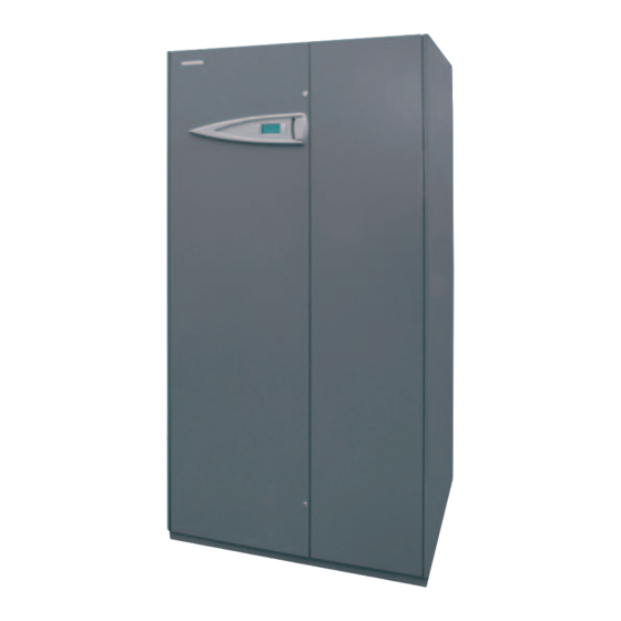
INSTALLATION MANUAL - USER AND MAINTENANCE
Precision air-conditioners
i-ACCURATE
i-AX
Direct Expansion
Air Cooled
i-AW
Direct Expansion
Water Cooled
i-AD
Dual Fluid
Air Cooled
i-AT
Dual Fluid
Water Cooled
i-AF
Free Cooling
Water Cooled
50/60Hz range
EN
frame 2:
12-18
frame 3:
20-29
frame 4:
50
frame 5:
70
frame 6:
90
frame 7:
130-150
Advertisement
Table of Contents

Related Manuals for CLIMAVENETA i-ACCURATE Series i-AX


Summary of Contents for CLIMAVENETA i-ACCURATE Series i-AX
- Page 1 INSTALLATION MANUAL - USER AND MAINTENANCE Precision air-conditioners i-ACCURATE i-AX Direct Expansion Air Cooled i-AW Direct Expansion Water Cooled i-AD Dual Fluid Air Cooled i-AT Dual Fluid Water Cooled i-AF Free Cooling Water Cooled 50/60Hz range frame 2: 12-18 frame 3: 20-29 frame 4: frame 5:...
-
Page 3: Table Of Contents
(whereas applicable). Contact Climaveneta Commercial Office for further drawings and schemes. Climaveneta declines any liability derived from the bulletin’s use. This bulletin is of exclusive property of Climaveneta, and all forms of copy are prohibited. The data contained herein are subject to variation without notice. -
Page 4: Documents
DOCUMENTS DOCUMENTS ENCLOSED WITH THE UNIT • List of spare parts; Each unit is delivered complete with the following documents: • CE declaration with list of European directives and standards • Air-conditioner installation - user and maintenance manual; that the unit is compliant with; •... - Page 5 COMPRESSORS REHEATING WITH HOT GAS COIL INVERTER-DRIVEN HERMETIC SCROLL and ON/OFF compres- Available as an alternative to the hot water coil, this is placed sors, complete with thermal protector. Fitted on rubber vibration downstream of the evaporator coil, and is used during dehumidifi- dampers and complete with oil charge.
- Page 6 REFRIGERANT CIRCUIT Note 1: unit and outdoor condensers supplied separately All models have a single refrigerant circuit, and in some cases, Note 2: the indoor unit is delivered charged with nitrogen at depending on the model, two circuits - 1 x ON/OFF + 1 x near-atmospheric pressure.
- Page 7 FREECOOLING UNITS – VERSION i-AF DUAL FLUID UNITS – VERSION i-AD (air-cooled) & The i-AF series units, in favourable outside conditions, can use the i-AT (water-cooled ) cooling water to maintain the set environmental conditions with- The i-AD and i-AT series units feature two different cooling sys- out the need for mechanical cooling using the compressor, or to tems, which cannot be active at the same time.
- Page 8 Version i-AT (water-cooled) The i-AT series units use water as the cooling fluid, therefore each refrigerant circuit is combined with a plate heat exchanger installed on the unit, suitably sized to ensure minimum water side pressure drop and consequently reduce the power consumption of the water pump.
-
Page 9: Air Flows
AIR FLOWS The i-ACCURATE air-conditioners are available in different erally have the air intake at the front, rear and/or from the bot- configurations, based on the air intake and outlet positions; the tom, as required by the customer, and the air outlet from the top main distinction is between OVER and UNDER units. -
Page 10: Rating Plate
Manual n° : Wiring Diagrams: rev. 36061 BASSANO DEL GRAPPA (VI) ITALIA - via SARSON, 57/C Tel.+39 0424 509500 Fax+39 0424 509509 e-mail: info@climaveneta.it TECHNICAL DATA ACCURATE - i-AX Air-cooled direct expansion unit TECHNICAL DATA Model Frame No. of circuits / no. of compressors... - Page 11 ACCURATE - i-AW Water-cooled direct expansion unit Model Frame No. of circuits / no. of compressors Refrigerant R410A R410A R410A R410A R410A R410A R410A R410A R410A Rated air flow-rate mc/h 3500 4900 6500 8000 13500 19000 25000 30000 30000 Power supply V/Ph/Hz 230/1/50 400/3N/50...
- Page 12 ACCURATE - i-AF Water-cooled direct expansion unit with indirect free cooling Model Frame No. of circuits / no. of compressors Refrigerant R410A R410A R410A R410A R410A R410A Rated air flow-rate mc/h 6500 8000 13500 19000 25000 28000 Power supply V/Ph/Hz 400/3N/50 CAPACITY DELIVERED Maximum speed...
- Page 13 ACCURATE - i-AD Air-cooled direct expansion unit Model Frame No. of circuits / no. of compressors Refrigerant R410A R410A R410A R410A R410A R410A Rated air flow-rate mc/h 6500 8000 13500 19000 25000 28000 Power supply V/Ph/Hz 400/3N/50 CAPACITY DELIVERED Maximum speed Gross total capacity (1) 18,89 27,50...
- Page 14 ACCURATE - i-AT Water-cooled direct expansion unit Model Frame No. of circuits / no. of compressors Refrigerant R410A R410A R410A R410A R410A R410A Rated air flow-rate mc/h 6500 8000 13500 19000 25000 28000 Power supply V/Ph/Hz 400/3N/50 CAPACITY DELIVERED Maximum speed Gross total capacity (1) 19,37 28,58...
-
Page 15: Hot Water Re-Heating
HOT WATER RE-HEATING Post reheating system by mean hot water, composed by finned coil with copper tubes, 3 way valve and actuator driven with the logic imple- mented in EVOLUTION+ controller PERFORMANCE Frame Modello Heating Capacity (4) 16,4 20,2 14,4 16,1 28,7 39,3... -
Page 16: Transport And Handling
TRANSPORT AND HANDLING Move the air-conditioner, which must not be reclined or tipped - using fabric slings underneath the unit, making sure that when over, nor exposed to the elements, as near as possible to the site the slings are in tension these do not apply pressure on the top of installation before removing the packaging and the pallet. -
Page 17: Dimensions And Weight
DIMENSIONS AND WEIGHT OVER Models Frame 2 OVER Models Frame 4 Ventilatori radiali EC EC Radial fan OVER Models Frame 3 EC Radial fan The drawings represent the configuration with air intake from the front. i-ACCURATE i-AX - i-AW - i-AD - i-AT - i-AF... - Page 18 OVER Models Frame 5 OVER Models Frame 6 EC Radial fan EC Radial fan OVER Models Frame 7 EC Radial fan The drawings represent the configuration with air intake from the front. i-ACCURATE i-AX - i-AW - i-AD - i-AT - i-AF...
- Page 19 UNDER Models Frame 2 UNDER Models Frame 3 UNDER Models Frame 4 i-ACCURATE i-AX - i-AW - i-AD - i-AT - i-AF...
- Page 20 UNDER Models Frame 5 UNDER Models Frame 6 UNDER Models Frame 7 i-ACCURATE i-AX - i-AW - i-AD - i-AT - i-AF...
-
Page 21: Positioning The Air-Conditioner
POSITIONING THE AIR-CONDITIONER The air-conditioner can rest directly on the floor, perfectly level, with a maximum difference in height of 5 mm between the ends of the base: incorrect levelling may cause the condensate to leak from the collection pan. WARNING: the air-conditioner must be installed indoors and in non-aggressive environments. -
Page 22: Operating Limits
OPERATING LIMITS All versions. The i-AX - i-AW - i-AF - i-AD - i-AT units are designed for operation within the following operating ranges (the limits are considered for new units that have been correctly installed and maintained): 46 °C Environmental conditions 35 °C from 20,0°C, 45% RH at 32°C, 55% RH... -
Page 23: Air Distribution (Under Units)
AIR DISTRIBUTION, UNDER UNITS (UNDER UNITS) In the units with air outlet from the bottom, the following details For units with air outlet from the bottom, the recommended air must be ensured to allow for sufficient air flow-rate: outlet speed from the raised floor is between 1 and 2.5 m/s; con- a) connection opening between the unit and the raised sequently, the cross-section of the grills should be sized based on floor;... -
Page 24: Motor-Driven Damper (Over/Under Units)
MOTOR-DRIVEN DAMPER OVER/UNDER (UNIT OVER/UNDER) La serranda motorizzata, disponibile come accessorio opzionale, è posta all'interno di un plenum alto 150 m. The OVER and UNDER units, models 12-90, are delivered with the damper already fitted, at the top of the unit, as shown in the figure. -
Page 25: Soundproof Suction Or Outlet Plenum
SOUNDPROOF SUCTION OR OUTLET PLENUM The figure shows the soundproof plenum to be installed on the top of the unit. Models L mm 1000 1550 2100 2650 P mm H mm DIRECT FREE COOLING PLENUM (UNDER UNITS) This accessory is installed on the top of the unit, and is used to WARNING: take in cool outside air and then deliver it directly into the air- For correct installation, an elastic gasket should be fitted between... -
Page 26: Direct Free Cooling Base (Over Units)
DIRECT FREE COOLING BASE (OVER UNITS) This accessory is installed on the BOTTOM of the unit, and is INSTALLATION EXAMPLE used to take in cool outside air and then deliver it directly into the air-conditioned environment. The plenum is supplied with 2 UNDER OVER motorised dampers (one for the outside air + 1 for the inside... - Page 27 OPTIONAL AIR FILTER The standard filter (G2/G4) and optional (F5/F6/F7/F8) are installed inside the conditioning unit before the finned coil. Additional pressure drop: Std G2 filter Std G4 filter Frame 2 Frame 5 6500 m³/h 3500 4000 4500 5000 5500 6000 9000 11000...
-
Page 28: Position And Diameter Of The Water Connections
POSITION AND DIAMETER OF THE WATER CONNECTIONS OVER CONNECTIONS (i-AX - i-AW) size 12-18 IN refrigerant i-AX OUT refrigerant i-AX IN water cooled i-AW OUT water cooled i-AW IN power supply IN humidifier water OUT humidifier water and condensate water drain IN hot water OHW OUT hot water PLAN VIEW... - Page 29 UNDER CONNECTIONS (i-AX - i-AW - i-AD - i-AT - i-AF) size 20-29 IN refrigerant i-AX - i-AD OUT refrigerant i-AX - i-AD IN water cooled i-AW OUT water cooled i-AW - i-AT -i-AF IN water i-AF - i-AT IN power supply IN humidifier water OUT humidifier water IN hot water...
- Page 30 OVER CONNECTIONS (i-AX - i-AW - i-AD - i-AT - i-AF) size 70 IN refrigerant circ. 1 i-AX - i-AD OUT refrigerant circ. 1 i-AX - i-AD IN refrigerant circ. 2 i-AX - i-AD OUT refrigerant circ. 2 i-AX - i-AD IN water cooled circ.
- Page 31 UNDER CONNECTIONS (i-AX - i-AW - i-AD - i-AT - i-AF) size 90 IN refrigerant circ. 1 i-AX - i-AD OUT refrigerant circ. 1 i-AX - i-AD IN refrigerant circ. 2 i-AX - i-AD OUT refrigerant circ. 2 i-AX - i-AD IN water cooled i-AW OUT water cooled i-AW - i-AT - i-AF IN water i-AF - i-AT...
-
Page 32: Water Connections
WATER CONNECTIONS For all the water connections (with the exception of the For i-AW - i-AF - i-AT models check that the water circuit condensate drain), the following are recommended: has been filled with an antifreeze mixture containing the - flexible connections to avoid transmitting vibrations and right percentage of ethylene glycol. - Page 33 Pressure Drops on stainless steel pipes (inch.) - Water T .= 10°C 12 14 16 18 500.000 500.000 400.000 400.000 300.000 300.000 200.000 200.000 100.000 100.000 90.000 90.000 80.000 80.000 70.000 70.000 60.000 60.000 50.000 50.000 40.000 40.000 30.000 30.000 20.000 20.000 10.000...
- Page 34 Pressure Drops on stainless steel pipes (inch.) - Water T .= 50°C 12 14 16 18 500.000 500.000 400.000 400.000 300.000 300.000 200.000 200.000 100.000 100.000 90.000 90.000 80.000 80.000 70.000 70.000 60.000 60.000 50.000 50.000 40.000 40.000 30.000 30.000 20.000 20.000 10.000...
- Page 35 Pressure Drops on stainless steel pipes (inch.) - Water T .= 80°C 12 14 16 18 500.000 500.000 400.000 400.000 300.000 300.000 200.000 200.000 100.000 100.000 90.000 90.000 80.000 80.000 70.000 70.000 60.000 60.000 50.000 50.000 40.000 40.000 30.000 30.000 20.000 20.000 10.000...
-
Page 36: Air Condenser: Suggested Installation
AIR CONDENSER: SUGGESTED INSTALLATION 1/100 1/100 air-conditioner discharge max 50 metres 1/100 1/100 air-conditioner max 5 metres outlet liquid 1/100 1/100 max 3 metres max 15 air-conditioner metres max 3 metres N.B.: Create traps as shown in the figure, making sure to fill them with oil when commissioning the system. Fit a non-return valve at the unit outlet, on the gas outlet pipe. -
Page 37: Refrigerant Connections
REFRIGERANT CONNECTIONS (i-AX / i-AD) Warning: All work must be performed, components selected and materials used in complete accordance with the legislation in force in material in the country concerned, and considering the operating conditions and intended uses of the system, by qualified personnel. The diameter of connecting pipes between the conditioner and condensing unit must be respected, otherwise the guarantee becomes invalid. -
Page 38: Oil Separator
OIL SEPARATOR On installations with air-cooled units (i-AX / i-AD) with remote condensers, if the refrigerant lines are more than 50 m long an oil separa- tor must be installed only on the circuit with ON/OFF compressor, to prevent lubricating oil from circulating in the system together with the refrigerant and possibly breaking the compressor. -
Page 39: Volume
VOLUME INDOOR COIL VOLUME AND REFRIGERANT CHARGE Indicative gas content Indicative gas content Models Models R410A (kg) R410A (kg) i-AX 12 i-AW 12 i-AX 18 i-AW 18 i-AX - i-AD 20 i-AW - i-AT - i-AF 20 i-AX - i-AD 29 i-AW - i-AT - i-AF 29 i-AX - i-AD 50 i-AW - i-AT - i-AF 50... -
Page 40: Electrical Connections
CONDENSATE DRAIN The condensate is removed from the pan located underneath the drained from the humidifier pan, excluding Over units (see the coil through a hose with drain trap, already fitted in the unit; the following paragraph). end of the hose should be connected to the sewerage system in During installation, pour water into the condensate collection pan the building via a rubber or plastic hose with an inside diameter so as to fill the drain trap inside the unit with water. -
Page 41: Electrical Specifications
MINIMUM CROSS-SECTION OF THE POWER CABLES The cross-section of the power cable must be chosen according - A backup fuse should be fitted upstream of the power to the length of the cable and the type of installation, based on line for short-circuit current up to 10 kA. - Page 42 POWER CONSUMPTION OF INDIVIDUAL COMPONENTS (COMPRESSOR) Unit power Vers. INVERTER compressor ON/OFF compressor supply Frame Mod. V/ph/Hz V/ph/Hz Qty. I@30Hz V/ph/Hz Qty. (kW) (kW) 230/1/50 230/1/50 25,1 12,1 400/3N/50 400/3/50 10,1 15,4 400/3N/50 400/3/50 10,1 15,4 400/3N/50 400/3/50 16,7 25,6 400/3N/50 400/3/50 19,02...
- Page 43 POWER CONSUMPTION OF INDIVIDUAL COMPONENTS (FAN) Vers. Unit power supply Std. EC radial fan HP EC radial fan Frame Mod. V/ph/Hz V/ph/Hz Qty. FLI (kW) FLA (A) V/ph/Hz Qty. FLI (kW) FLA (A) 230/1/50 230/1/50 0,48 230/1/50 3,15 400/3N/50 230/1/50 0,48 230/1/50 3,15...
- Page 44 POWER CONSUMPTION OF INDIVIDUAL COMPONENTS (HEATERS) Vers. Unit power supply STD electric heaters HIGH POWER electric heaters Frame Mod. V/ph/Hz V/ph/Hz Qty. FLI (kW) FLA (A) V/ph/Hz Qty. FLI (kW) FLA (A) 230/1/50 230/1/50 23,5 230/1/50 34,8 400/3N/50 230/1/50 34,8 230/1/50 17,3 400/3N/50...
- Page 45 POWER CONSUMPTION OF INDIVIDUAL COMPONENTS (HUMIDIFIER) Vers. Unit power supply Humidifier modulating Frame Mod. V/ph/Hz V/ph/Hz Qty. FLI (kW) FLA (A) kg/h 230/1/50 230/1/50 2,25 400/3N/50 400/3/50 3,75 400/3N/50 400/3/50 3,75 400/3N/50 400/3/50 3,75 400/3N/50 400/3/50 3,75 400/3N/50 400/3/50 400/3N/50 400/3/50 400/3N/50 400/3/50...
- Page 46 ELECTRICAL CONNECTION OF THE i-BRE and BRE OUTDOOR AIR-COOLED CONDENSERS and/or i-BDC and BDC OUTDOOR DRY COOLERS It must be stressed that both the standard air-cooled condensers 10V signal, following the logic implemented on the EVOLUTION+ and dry coolers supplied by the manufacturer are not fitted as controller.
- Page 47 VACUUM AND CHARGE The refrigerant circuits of the water-cooled chillers and air-condi- that require refrigerant connections to other units are pre- tioners are already charged with refrigerant, either R410A or charged with nitrogen (or dry air) to prevent moisture from R410A (check the rating plate on the unit and the compressors entering the circuit;...
-
Page 48: Operation And Control
OPERATION AND CONTROL WATER-COOLED UNITS Water in an open circuit If the temperature of the cooling water is not controlled and may fall below 25°C, a pressure control valve is required (available as an accessory) for each condenser; in this case, the supply pressure must not be less than 200 kPa (2 bar). -
Page 49: Instruments And Alarms
INSTRUMENTS AND ALARMS The air-conditioner is fitted with the following instruments: In addition, the following optional devices may be available: - High pressure switch/switches with manual reset (one on - Flood sensor made up of: each refrigerant circuit); a) device to be inserted in the special socket on the electrical - Low pressure switch/switches with automatic reset (one panel;... -
Page 50: Calibrating The Control And Safety Devices
CALIBRATING THE CONTROL AND SAFETY DEVICES After starting the air-conditioner, make the following adjustments The calibration values of the control and safety devices must not - Room temperature (cooling and heating set point). be altered. - Relative humidity (set point for humidification and dehumidifi- cation);... -
Page 51: Calibrating The Air Flow Sensor
CALIBRATING THE AIR FLOW SENSOR The differential pressure switch F3 must be activated if the fan is To calibrate the pressure switch, remove the plastic cover (A) by not working (when there is one fan) or one of the fans is not unscrewing the two screws (B). -
Page 52: Temperature And Humidity Probe
TEMPERATURE AND HUMIDITY PROBE The figure shows the optional temperature and humidity probe. For the probe electrical connection use a shielded cable; the con- If having to replace the probe, release the white plastic cover by nections to the terminals on the board are shown on the wiring pressing point (A) with a screwdriver or a pointed object;... - Page 53 Type Rated voltage Run time at 50 Hz Control signal SSB81 AC 24 V 150 s 3-position SSB61 AC/DC 24 V 75 s DC 0...10 V Description Manual override This actuator with 3point or 0÷10V signal is adapt for 2 or 3 way valve with 5,5mm stroke 3 mm Function...
- Page 54 Type Rated voltage Run time at 50 Hz Control signal SSB81 AC 24 V 150 s 3-position SSB61 AC/DC 24 V 75 s DC 0...10 V Description Manual override This actuator with 3point or 0÷10V signal is adapt for 2 or 3 The rotary knob can be used to drive the actuator into any way valve with 5,5mm stroke position between 0 and 1.
- Page 55 Description This actuator with 3point or 0÷10V signal is adapt for 2 or 3 way valve with 20mm stroke SQX82: SQX62: Terminal strip Button S3 (calibration) LED, red / green (operating status indication) Terminal strip DIL switches: S1: change-over flow characteristic «LOG» / «LIN» *) S2: change-over signal R «0-10 V, 4-20 mA»...
- Page 56 Indication of operating state SQX62 Indication Function Remarks, troubleshooting Control mode Automatic operation; everything o.k. Green Flashing Calibration Wait until calibration is finished Internal error Troubleshooting, eventually replace actuator Troubleshooting, recalibrate Flashing Calibration error (operate button S3 1x) No power supply Check mains network, check wiring Both Dark...
-
Page 57: Electric Heaters
ELECTRIC HEATERS ELECTRIC HEATERS The overall power of the electric heaters is divided into a number of elements, each with a power of 2÷3÷4 kW. The colour of the wires on each element has the following mean- ing: • BLACK wire = low power element (0,7÷1÷1,3 kW); •... - Page 58 HUMIDIFIER OPERATING PRINCIPLE STEAM CYLINDER In the immersed electrode humidifier, the current that runs The steam cylinder requires periodical cleaning to remove the between the electrodes, through the water contained in the boil- scale deposits that form on the surface of the electrodes and the er cylinder, generates the heat required to boil the water.
-
Page 59: Humidifier Power Supply
HUMIDIFIER POWER SUPPLY Underneath the fill solenoid valve on the steam production unit is the threaded male fitting (V) for the humidifier water supply. position: V-F Ø 32mm This is already fitted with a plastic hose, diameter 6 mm, for con- nection to the building's water supply (see figure, point F). -
Page 60: Std Condensate Drain Pump (Low Water Temperature)
CONDENSATE DRAIN PUMP AND HUMIDIFIER DRAIN PUMP Depending on the version, a condensate drain pump is available The pump must be located below the drain fitting, according to (for versions B and R) or a humidifier drain pump (for versions H the instructions contained in the packaging. -
Page 61: Condensate Drain Pump For High Water Temp
CONDENSATE DRAIN PUMP FOR HIGH WATER TEMP. (HUMIDIFIER) SAFETY SWITCH BLACK BLACK PUMP LINE MOTOR PUMP START NEUTRAL SWITCH EARTH PUMP FRAME These pumps are designed to collect the hot water produced by the humidifier drain cycles, as well as the condensate produced. Maintenance guide The pump body is made from Cycoloy, a heat-resistant material, At least once every 6 months, pour a bactericidal solution into... - Page 62 DOUBLE POWER SUPPLY WITH AUTOMATIC SWITCHING The motorised changeover switches automatically manage • The model supplied in the automatic version checks the source changeover under load between two single-phase or three-phase and switches over automatically, based on the configurable para- power supplies, or manually for emergency operations.
-
Page 63: Maintenance
MAINTENANCE the water inlet and outlet temperature and compare it against the Every components replacement (compressor, safety presso- condensing temperature. stat, liquid receiver, ecc.) have to consider the main compo- Normally, for good heat exchange, the difference between the nent list enclosed in the unit. water outlet temperature and the condensing temperature must be 5.8°C. -
Page 64: Troubleshooting
TROUBLESHOOTING Troubleshooting is simplified by the information provided by the If required, contact the nearest service centre, indicating the microprocessor controller: if an alarm is signalled, refer to the probable causes of the fault. control panel instruction manual. FAULT CAUSE SOLUTION THE AIR-CONDITION- The electrical panel is not powered... - Page 65 FAULT CAUSE SOLUTION AMBIENT HUMIDITY The parameter settings on the See the controller manual. TOO HIGH microprocessor controller are not correct. Latent load higher than expected Check and calculate the latent load; check the flow-rate and the conditions of the outside air; check the inflow of outside air.
- Page 66 FAULT CAUSE SOLUTION HEATER SAFETY Insufficient air flow-rate See “LOW OR NO AIR FLOW”. THERMOSTAT ACTIVATED Check the continuity of the connection from Thermostat connection wire cut or broken the safety thermostat to the control system. Faulty thermostat Replace the heater safety thermostat. HIGH COMPRESSOR A) Air or incondensable gas in the refrigerant DISCHARGE...
- Page 67 FAULT CAUSE SOLUTION LOW COMPRESSOR Check the calibration and the operation of the The condensing pressure control system DISCHARGE condenser fan pressure switch or the speed isn't working (see the control panel manual). PRESSURE controller; Excessive water flow-rate to the condenser Check the temperature of the cooling water.
- Page 68 Climaveneta Deutschland GmbH Lyrenstraße 13 44866 Bochum Germany Tel +49 2327-95428-0 Fax +49 2327-95428-99 info@climaveneta.de www.climaveneta.de Climaveneta España - Top Clima Londres 67, 1 4 08036 Barcelona Spain Tel +34 934 195 600 Fax +34 934 195 602 topclima@topclima.com www.climaveneta.com Climaveneta Chat Union Refrig.
Need help?
Do you have a question about the i-ACCURATE Series i-AX and is the answer not in the manual?
Questions and answers