Table of Contents
Advertisement
Quick Links
WARNING
Improper installation, adjustment, alteration, service
or maintenance can result in death, injury or
property damage. Read the Installation, Operation
and Service Manual thoroughly before installing or
servicing this equipment.
Installation must be done by an electrician qualified
in the installation and service of control systems
for heating equipment.
© 2014 Roberts-Gordon Europe Limited
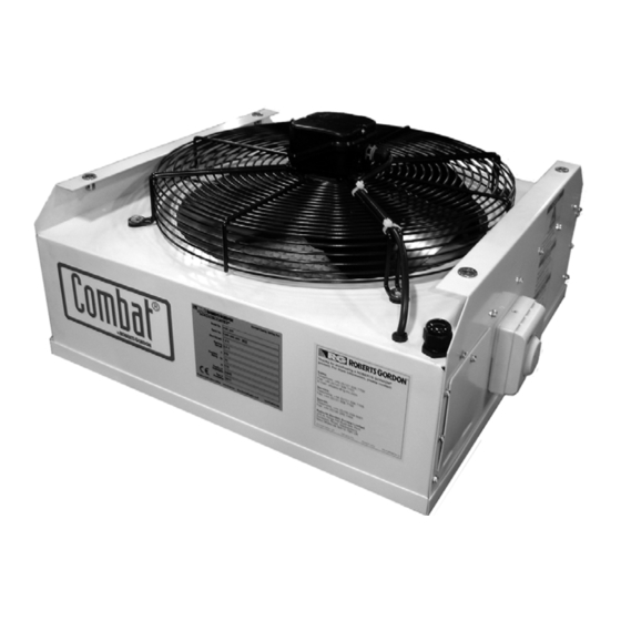
Combat
Energy Saving Fans
with Control Options
Installation, Operation &
Please take the time to read and understand
these instructions prior to any installation.
Installer must give a copy of this manual to the owner.
Keep this manual in a safe place in order to provide
your service technician with necessary information.
Roberts-Gordon Europe Limited
Unit A, Kings Hill Business Park
Darlaston Road, Wednesbury
West Midlands, WS10 7SH UK
Telephone: +44 (0)121 506 7700
Fax: +44 (0)121 506 7701
Service Telephone: +44 (0)121 506 7706
Service Fax: +44 (0)121 506 7702
E-mail: uksales@rg-inc.com
E-mail: export@rg-inc.com
www.robertsgordon.co.uk
www.blackheatheaters.co.uk
®
HVE
Service Manual
Installer
Owner
P/N 160101UK Orig 07/14
Advertisement
Table of Contents

Summary of Contents for Roberts Gorden Combat HVE 400
-
Page 1: Service Manual
® Combat Energy Saving Fans with Control Options Installation, Operation & Service Manual WARNING Installer Please take the time to read and understand Improper installation, adjustment, alteration, service these instructions prior to any installation. or maintenance can result in death, injury or Installer must give a copy of this manual to the owner. -
Page 3: Table Of Contents
TABLE OF CONTENTS SECTION 1: Introduction............2 1.1 Electrical Requirements ..........2 1.2 Check Installation Materials ......... 2 1.3 Safety Labels and Their Placement ......3 SECTION 2: Specifications ............ 4 2.1 Electrical Specifications ..........4 2.2 Fan Specifications............4 2.3 Dimension Data ............ - Page 5 TABLE OF FIGURES Figure 1: Label Placement ............3 Figure 2: Dimension Data ............4 Figure 3: Mounting Hole Layout..........6 Figure 4: Suspension Methods ..........7 Figure 5: BJ8 Fan Control Wiring Diagram........ 8 Figure 6: DP5 Fan Control Wiring Diagram....... 8 Figure 7: WAC6 Fan Control Wiring Diagram......
- Page 7 Product Approval ® ROBERTS GORDON appliances have been tested and CE certified as complying with the essential requirements of the Gas Appliance Directive, the Low Voltage Directive, the Electromagnetic Compatibility Directive and the Machinery Directive for use on natural gas and LPG when installed, commissioned and maintained in accordance with these instructions.
-
Page 8: Section 1: Introduction
YSTEM ONTROL NSTALLATION PERATION AND ERVICE ANUAL SECTION 1: INTRODUCTION Your Safety is Important to Us! 1.1 Electrical Requirements This symbol is used throughout DANGER the manual to notify you of possible fire, electrical or burn hazards. Please pay special atten- tion when reading and following the warnings in these sections. -
Page 9: Safety Labels And Their Placement
SECTION 1: I NTRODUCTION 1.2.2 Electrical Installation Materials A 230 V, 50 Hz, 1 ph, 20 A power supply to equipment must be installed and comply with current wiring regulations and any local regulations which may apply. 1.3 Safety Labels and Their Placement Product safety signs or labels should be replaced by product user when they are no longer legible. -
Page 10: Section 2: Specifications
YSTEM ONTROL NSTALLATION PERATION AND ERVICE ANUAL SECTION 2: SPECIFICATIONS 2.1 Electrical Specifications Supply: 230 V, 50 Hz, 1 Ø, 20 A 2.2 Fan Specifications Model HVE 400 HVE 450 HVE 650 3,600 6,300 10,800 Air Capacity /min] 2,120 3,710 6,360 Fan Diameter [mm]... -
Page 11: Section 3: Critical Considerations
SECTION 3: C RITICAL ONSIDERATIONS SECTION 3: CRITICAL CONSIDERATIONS 3.1 Location and Suspension All models: • Must be installed indoors. • Must be installed in a level position. • Fan must be suspended from above (See Page 7 , Figure 4). Drop rods must be a minimum of 10 mm diameter mild steel. -
Page 12: Section 4: Installation
YSTEM ONTROL NSTALLATION PERATION AND ERVICE ANUAL SECTION 4: INSTALLATION mm diameter mild steel. Four suspension points (M10 nuts) are located on top of fan. Mounting DANGER hardware must be sufficient to support fan weight as listed in the dimension data on Page 4, Sec- tion 2.3. -
Page 13: Electrical Supply
SECTION 4: I NSTALLATION FIGURE 4: Suspension Methods 4.2 Electrical Supply All fans and controls need a constant 230 V 50 Hz single phase supply connected to terminals L, N, and Earth. Polarity "L & N" must be correct. The voltage between neutral and earth should be 0 and never exceed 15 volts. -
Page 14: Section 5: Typical External Wiring Diagrams
YSTEM ONTROL NSTALLATION PERATION AND ERVICE ANUAL SECTION 5: TYPICAL EXTERNAL WIRING 5.1 External Wiring Connection Details DIAGRAMS If any of the original wire supplied with fan must be replaced, it must be replaced with wiring material DANGER having a temperature rating of at least 105 °C and 600 V. -
Page 15: Figure 7: Wac6 Fan Control Wiring Diagram
SECTION 5: T YPICAL XTERNAL IRING IAGRAMS FIGURE 7: WAC6 Fan Control Wiring Diagram FIGURE 8: HVE Fan Without Speed Control Wiring Diagram 9 of 12... -
Page 16: Section 6: Troubleshooting
YSTEM ONTROL NSTALLATION PERATION AND ERVICE ANUAL SECTION 6: TROUBLESHOOTING DANGER Electrical Shock Hazard Disconnect electric before service. More than one disconnect switch may be required to disconnect electric to the unit. Failure to follow these instructions can result in death or electrical shock. 6.1 Sequence of Operation The BJ8 Fan Control uses an external temperature sensor to automatically adjust HVE Fan speed. -
Page 17: Section 7: Replacement Parts
SECTION 7: R EPLACEMENT ARTS SECTION 7: REPLACEMENT PARTS WARNING DANGER Electrical Shock Hazard Explosion Hazard Carbon Monoxide Hazard Fire Hazard Use only genuine ROBERTS GORDON ® replacement parts per this installation, operation and service manual. Failure to follow these instructions can result in death, electric shock, injury or property damage. DANGER Electrical Shock Hazard Disconnect electric before service. -
Page 18: Figure 9: Internal Components Diagram
YSTEM ONTROL NSTALLATION PERATION AND ERVICE ANUAL FIGURE 9: Internal Components Diagram Model Description Part Number HVE 400 Axial Fan 400 mm A263A HVE 450 Axial Fan 450 mm A268A HVE 650 Axial Fan 650 mm A269 Thermostat 230 V C2334B 12 of 12...
Need help?
Do you have a question about the Combat HVE 400 and is the answer not in the manual?
Questions and answers