Table of Contents
Advertisement
Advertisement
Table of Contents

Summary of Contents for HH Electronic PERFORMER
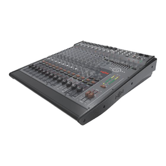
- Page 1 P E R F O R M E R P E R F O R M E R - F X OWNERS MANUAL...
-
Page 3: Table Of Contents
Important Safety Instructions - Part 2 Foreword Introduction 7-8. Mono Input 9-10. Stereo Input / USB FX Send / Return Onboard FX (Performer FX only) Aux Masters / EQ I/O Connections Masters / Connection summary Connection diagram 17-18. Quick Start Trouble shooting... - Page 4 SAFETY / DE SECURITE IMPORTANT SAFETY INSTRUCTIONS WARNING: When using electrical products, basic cautions should always be followed, including the following: 1. Read these instructions. 2. Keep these instructions safe. 3. Heed all warnings. 4. Follow all instructions. 5. Do not use this apparatus near water. 6.
- Page 5 SICHERHEITSHINWEISE / SU SEGURIDAD WICHTIGE SICHERHEITSHINWEISE - DEUTSCH ACHTUNG: Beim Einsatz von Elektrogeräten müssen u.a. grundlegende Vorsichtsmaßnahmen befolgt werden: durch. 1. Lesen Sie sich diese Anweisungen 2. Bewahren Sie diese Anweisungen auf. 3. Beachten Sie alle Warnungen. 4. Befolgen Sie alle Anweisungen. 5.
-
Page 6: Important Safety Instructions - Part
IMPORTANT SAFETY INSTRUCTIONS PT 2 Intended to alert the user to the presence of uninsulated ‘Dangerous Voltage’ within the products enclosure that may be sufficient to constitute a risk of electrical shock to persons. Ce symbole est utililise pur indiquer a l’utilisateur de ce produit de tension non-isolee dangereuse pouvant etre d’intensite suffisante pour constituer un risque de choc electrique. -
Page 7: Foreword
FOREWORD Thank you for choosing to purchase an HH product. We at HH are guided by the principle that all of our products must balance the elements of ‘Head’ and ‘Heart: ‘Head’ is about finding the right specifications, the right engineering solutions, the right manufacturing techniques and of course the right price. -
Page 8: Introduction
PERFORMER range of mixers feature stunning sound, rugged build quality and a host of imaginative, usable features. The PERFORMER mixer is a fantastic building block for your sound, ideal for musicians who need flexibility as well as for venues and hire companies who need a reliable and dependable mixing tool. -
Page 9: Mono Input
MONO INPUT 1) MIC INPUT (XLR) Designed to accept both balanced and unbalanced signals from microphones with an XLR input connector. Good quality low impedance condenser or dynamic mic's should preferably be used for best effect, these will ensure the best possible results from hand held vocals or closely mic'd instruments. - Page 10 MONO INPUT CONTINUED 9) AUX SENDS Pre fade/post EQ operation, meaning the Aux levels are set via the Aux Send pot, but not affected by the channel fader. 10) FX SENDS Post fade/post EQ operation, meaning the FX levels is set via the FX Send pot and is also dependant on the Input channel fader.
-
Page 11: Stereo Input / Usb
STEREO INPUT USB I/O Stereo input channel’s 11/12 are equipped with USB I/O. To use this feature, connect USB audio to the provided socket and press in the Mono / Stereo USB switch. The signal will be processed and routed to the MIC (left) and LINE (right) inputs signal paths. - Page 12 STEREO INPUT CONTINUED 7) EQUALISATION A four band EQ system with ±12dB cut and boost is provided in each band. / Treble frequencies are boosted or cut using this control. Its centre frequency is 12K. Sources falling into this range include cymbals, soprano vocals. HI MID 2k25Hz.
-
Page 13: Fx Send / Return
RETURN connectors. From here they are internally routed to the MIX L and R busses. The SEND and RETURN (Performer-FX only) run in parallel to the internal DSP, meaning internal DSP and outboard FX can be used at the same time. -
Page 14: Onboard Fx (Performer Fx Only)
A dual foot-switch (FS-2) with latching switches is required. A short between tip and sleeve will DISABLE internal FX1. A short between ring and sleeve will DISABLE internal FX2. REMOTE (*1) Please note: only the ‘Performer-FX’ includes onboard digital FX. - Page 15 AUX MASTERS AND GRAPHIC EQ MAIN EQ 1) ALT OUT This controls the level for the ALT OUT sockets.. The ALT OUT takes its signal from the MIX OUT, but is not affected by the Master faders. 2) MIX / AUX This switch determines the source of the RECORD OUT.
-
Page 16: I/O Connections
I/O CONNECTIONS 1) FX SEND The signal is fed from here to the input of an outboard FX unit. 2) FX RETURN INPUTS The return signals from and external FX unit. The left is routed to the MAIN LEFT bus and right to the MAIN RIGHT. -
Page 17: Masters / Connection Summary
MASTERS / CONNECTION SUMMARY 1) OUTPUT LEVEL METERS By default, these meters monitor the MAIN LEFT and RIGHT signals. 2) PFL / AFL If either PFL or AFL is enabled anywhere on the console, the signal level will be displayed on the left meter, with the sum of MAIN LEFT and RIGHT visible on the right meter. -
Page 18: Connection Diagram
Designed with Head & Heart in the UK. WWW.HHELECTRONICS.COM 30 WATTS 50/60Hz Foot-switch HH Active PA or power-amp and passive PA.These could be used for stereo side fills or a feed to an alternative zone. Only the Performer FX requires a foot-switch remote. -
Page 19: Quick Start
QUICK START Switching on your mixer. The power socket and mains switch is located on the rear of the console. T1A L 250V MAINS SUPPLY VOLTAGE & FUSE RATING ~100V > ~240V POWER MAXIMUM POWER CONSUMPTION 30 WATTS 50/60Hz 1) Setting The Channel 1.1) Set the Master Faders to minimum. - Page 20 6) FX Sends Two FX sends are provided for your use. The Performer-FX can utilise its onboard FX, additional outboard FX or a combination of the two. Both sends are post fade so the relationship between the clean signal and effected signal remains constant whatever the position of the channel fader.
-
Page 21: Trouble Shooting
TROUBLE SHOOTING Below is a simple trouble shooting guide. Should you have problems in either initial setting up or at some future time, check out the problem by using the following suggestions: NO SOUND Is the power on? Are the correct channels 'ON'? Are the Master L+R outputs muted? Are the speakers connected? Are your connectors wired correctly? -
Page 22: Side Cheek To Rack Ear Change Over
SIDE CHEEK TO RACK EARS CHANGE-OVER Your Performer mixer can be desk or rack mounted. Rack mounting will require removal of the fitted side cheeks. Remove the 4 off M4 x 10mm screws Carefully remove the side cheek. Fit the rack ear using the same M4 x 10... -
Page 23: Performer-Fx Block Diagram
PERFORMER-FX BLOCK DIAGRAM... -
Page 24: Performer Block Diagram
PERFORMER BLOCK DIAGRAM... -
Page 25: Cue Sheet
CUE SHEET Copy this cue sheet and use it to keep a record of your mixer control setup. -
Page 26: Technical Specifications
TECHNICAL SPECIFICATION Gain and input impedance: variable from +10dB to +60dB Input impedance 3k3 Line variable from -10dB to +20dB Input impedance 35k -20dB switchable THD+N: 0dB in +18dB out @1kHz Mic to Mix 0.009% Frequency response: Measured from a 200 ohm source, - EQ flat - 20hz to 20kHz Mic to Mix +0 -1dB Maximum output levels:...
Need help?
Do you have a question about the PERFORMER and is the answer not in the manual?
Questions and answers