Advertisement
Quick Links
Advertisement

Subscribe to Our Youtube Channel
Summary of Contents for Extech Instruments 380820
- Page 1 User's Guide Universal AC Power Source + AC Power Analyzer Model 380820...
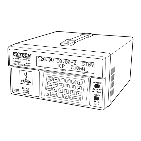
- Page 2 Introduction Congratulations on your purchase of the Extech Model 380820. This Universal AC Power Source and AC Power Analyzer can be used to test products in the range of 85 to 250VAC with a frequency range of 45 to 65Hz. This unit also features a...
-
Page 3: Safety Symbols
Please read the statement thoroughly to prevent injury or loss of life, and prevent damage to this product. Earth/Ground Terminal AC (Alternating Current) This unit has been tested and meets or exceeds the following standards: 1. EN61326-1: 2006: (CISPR11, IEC/EN 61000-3-2:2006, IEC/EN 61000-3-3: 1995+A1: 2001+A2: 2005 IEC/EN 61000-4-2/-3/-4/-5/-6/- 2. EN61010-1: 2001 380820-en-GB_V1.5 3/15... -
Page 4: Front Panel Description
OUTPUT FRONT/REAR: Selects the output. Press downward to display the Rear Output status. Press upward to display the Front Output status. : Increases a value. : Decrease a value. 11. POWER ON/OFF: Press to switch the supply ON or OFF. 12. V.ENTER: Press to confirm a program entry. 380820-en-GB_V1.5 3/15... - Page 5 Voltage Switch: Selects the voltage (110 or 220V) of the input power. Rear Output Socket CAUTION! The rear output socket is “LIVE” whenever the instrument power cord is plugged in even when the power supply is shut off. 380820-en-GB_V1.5 3/15...
-
Page 6: Operation
Leave at least 2” (5 cm) of space for good ventilation. Basic Test Setup Diagram Connect the Unit Under Test to the 380820. Front and Rear Output Select When the unit is switched ON, use the OUTPUT button to select the display for the Front or Rear output data. - Page 7 ▲▼to increase or decrease the value. Note: This setting will affect the REAR Output power measurements when frequency is involved. When monitoring the REAR output power, set the Frequency output setting to that of the incoming Line voltage. 380820-en-GB_V1.5 3/15...
- Page 8 2. Select the desired memory location (1 to 99) using the numeric keypad. 3. Press the V.ENTER button to confirm. The previously stored voltage/frequency configuration for the selected memory location will now be recalled. Note: For an empty memory location, the LCD will display ‘BLANK’ 380820-en-GB_V1.5 3/15...
- Page 9 3. In the OPER Mode, press the OPER/STBY button. The cost for the tested instrument per DAY/ MONTH/ YEAR will be displayed (left to right). 4. Press the $ button again to return to the normal power data display mode. 380820-en-GB_V1.5 3/15...
- Page 10 (n=1~50). Use the ▲▼ buttons to select the harmonics to be displayed. When the FUNC button is pressed again, the LCD will display the value of Current. Press the FUNC button again, the LCD will return to the power source display for the Rear Output. 380820-en-GB_V1.5 3/15...
- Page 11 5 minutes after power is switched ON. PC Interface for Data Acquisition The 380820 can be connected to a PC where readings can be logged in real-time as they are taken. Transferred reading data can be viewed, plotted, statistically analyzed, printed, and saved in the software program included with the unit.
-
Page 12: Specifications
A: ±4% of reading ±0.3A 0.1mA/ 0.001A/ 0.01A Hn (21 – 50 mA: ±10% of reading ±5mA Amp range A: ±10% of reading ±0.3A Hn (21 –50 mA: ±20% of reading ±5mA mA range A: ±20% of reading ±0.3A 380820-en-GB_V1.5 3/15... - Page 13 Operation Temperature: 4C to 60C (40°F to 140°F) Accessories: Power cord, Software CD-ROM, RS232C to USB cable Dimensions: 260mm x 151mm x 305 mm (10.2” x 5.9” x 12.0”) Weight: 9.9 kg s (21.8 lb) Copyright © 2012‐2015 FLIR Systems, Inc. All rights reserved including the right of reproduction in whole or in part in any form ISO‐9001 Certified www.extech.com 380820-en-GB_V1.5 3/15...
Need help?
Do you have a question about the 380820 and is the answer not in the manual?
Questions and answers