Table of Contents
Advertisement
Quick Links
MANUAL NO:P30051
OWNER'S
MANUAL
FOR
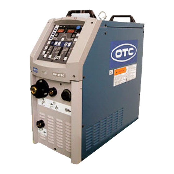
DIGITAL INVERTER
MAG
DP270C
MODEL: DP-270C
P30051
INVERTER CONTROLLED WELDING POWER SOURCE
DO
NOT
DESTROY
IMPORTANT:
Read and understand the entire contents of this
manual, with special emphasis on the safety material throughout
the manual, before installing, operating, or maintaining this
equipment. This equipment and this manual are for use only by
persons trained and experienced in the safety operation of welding
equipment. Do not allow untrained persons to install, operate or
maintain this equipment. Contact your distributor if you do not
fully understand this manual.
DAIHEN Corporation
WELDING PRODUCTS DIVISION
July 8, 2008
Upon contact, advise MODEL and MANUAL NO.
12-2-095-1
Advertisement
Table of Contents

Summary of Contents for OTC DP270C
- Page 1 MANUAL NO:P30051 OWNER'S MANUAL DIGITAL INVERTER DP270C MODEL: DP-270C P30051 INVERTER CONTROLLED WELDING POWER SOURCE DESTROY IMPORTANT: Read and understand the entire contents of this manual, with special emphasis on the safety material throughout the manual, before installing, operating, or maintaining this equipment.
-
Page 2: Table Of Contents
No. P30051 TABLE OF CONTENTS 1. SAFETY INFORMATION…………………………………………………………… 2 2. ARC WELDING SAFETY PRECAUTIONS……………………………………… 3. GENERAL NOTICE OF OPERATION…………………………………………….. 8 4. STANDARD COMPOSITION AND ACCESSORIES…………………………… 5. FUNCTION OF EQUIPMENT……………………………………………………… 11 6. NECESSARY POWER SOURCE EQUIPMENT………………………………… 13 7. TRANSPORT AND INSTALLATION……………………………………………… 14 8. -
Page 3: Safety Information
No. P30051 1. SAFETY INFORMATION The following safety alert symbols and signal words are used throughout this manual to identify various hazards and special instructions. WARNING gives information regarding possible personal injury WARNING or loss of life. CAUTION refers to minor personal injury or possible equipment CAUTION damage. - Page 4 No. P30051 2. ARC WELDING SAFETY PRECAUTIONS (continued) ELECTRIC SHOCK can kill. Touching live electrical parts can cause fatal shocks or severe burns. The electrode and work circuits are electrically live whenever the output is on. The power line and internal circuits of this equipment are also live when the line disconnect switch is on.
- Page 5 No. P30051 2. ARC WELDING SAFETY PRECAUTIONS (continued) WELDING can cause fire and explosion. Sparks and spatter fly off from the welding arc. The flying sparks, hot metal, spatter, hot base metal and hot equipment can cause fire and explosion. Accidental contact of electrode or welding wire to metal object can cause sparks, overheating, or fire.
- Page 6 No. P30051 2. ARC WELDING SAFETY PRECAUTIONS (continued) CYLINDER can explode if damaged. A shielding gas cylinder contains high-pressure gas. If damaged, a cylinder can explode. Since gas cylinders are normally part of the welding process, be sure to handle them carefully. Use only correct shielding gas cylinders, gas regulator, hoses, and fittings designed for the specific application;...
- Page 7 No. P30051 2. ARC WELDING SAFETY PRECAUTIONS (continued) ARC WELDING work areas are potentially hazardous. FALLING or MOVING machines can cause serious injury. 1. When hanging the welding power source by a crane, do not use the carrying handle. 2. Put the welding power source and wire feeder solidly on a flat surface. 3.
- Page 8 No. P30051 PRINCIPAL SAFETY STANDARDS Arc welding equipment – Installation and use, Technical Specification IEC 62081, from International Electro technical Commission Arc welding equipment Part 1: Welding power sources IEC 60974-1, from International Electro technical Commission Arc welding equipment Part 10: Electromagnetic compatibility (EMC) requirements IEC 60974-10, from International Electro technical Commission Safety in Welding and Cutting, ANSI Standard Z49.1, from American Welding Society.
-
Page 9: General Notice Of Operation
No. P30051 3. GENERAL NOTICE OF OPERATION 3.1 Rated Duty Cycle CAUTION Use this welding power source at or under the rated duty cycle. Exceeding the rated duty cycle limitation may result in damage to the welding machine. • The rated duty cycle of the welding power source is the following: 270A 40 •... -
Page 10: Standard Composition And Accessories
No. P30051 4. STANDARD COMPOSITION AND ACCESSORIES 4.1 Standard Composition • Preparation of the standard parts except the welding power source is required to use the welding power source. Gas regulator Gas hose * 400V 3 Grounding cable Analog remote control * Shield gas Input cables Welding torch... - Page 11 No. P30051 4. STANDARD COMPOSITION AND ACCESSORIES (continued) 4.3 Accessory Make sure you have the items below before you start using the welding power source. • Accessory of welding power source Description Specification Q’ty Part number Remarks For the fan on the rear side of Dust filter P30051J05 welding power source...
-
Page 12: Function Of Equipment
No. P30051 5. FUNCTION OF EQUIPMENT 5.1 Welding Power Source(Front side , back side) ―11―... - Page 13 No. P30051 5. FUNCTION OF EQUIPMENT (continued) 5.2 Welding Power Source (Left side) ―12―...
-
Page 14: Necessary Power Source Equipment
No. P30051 6. NECESSARY POWER SOURCE EQUIPMENT 6.1 Welding Power Source Equipment (for commercial use) WARNING When the welding machine is used in a humid environment such as a construction site, on a steel plate, or on a steel structure, install a leakage breaker. CAUTION Be sure to install a switch with fuse or a circuit breaker (for motor) to the input sides of each welding machine. -
Page 15: Transport And Installation
No. P30051 7. TRANSPORT AND INSTALLATION 7.1 Transport WARNING Follow the instructions below to avoid trouble and product damage when carrying the welding machine. Do not touch the live electrical parts inside or outside the welding machine. Be sure to disconnect the line disconnect switch when carrying the welding machine. - Page 16 No. P30051 7. TRANSPORT AND INSTALLATION (continued) CAUTION To prevent electromagnetic troubles, read the following. Also, if electromagnetic troubles occur, check the following again. Since large current abruptly flows inside the welding machine during welding, other machines near the welding power source may be troubled due to electromagnetic noise Do not ground the welding power source commonly with other machines.
-
Page 17: Connection Procedure And Ground For Safety Use
No. P30051 8. CONNECTION PROCEDURE AND GROUND FOR SAFETY USE WARNING Follow the instructions below to avoid electric shock. ∗ Do not touch the live electrical parts, as this will result in fatal shock and severe burn. Do not touch the live electrical parts of the welding machine. Have a qualified electric engineer ground the case of the welding power source and the base metal or jig electrically connected, following a local low. - Page 18 No. P30051 8. CONNECTION PROCEDURE AND GROUND FOR SAFETY USE 8.1.3 TIG welding Gas regulator Gas hose Analog remote control (Optionally available) Shield gas Welding torch Welding Power source Base metal Power cable for base metal 8.2 Connecting of the Gas Hose WARNING There is a danger of suffocation caused by lack of oxygen when shield gas is left flowing in a closed place.
- Page 19 No. P30051 8. CONNECTION PROCEDURE AND GROUND FOR SAFETY USE (continued) 8.3 Connecting of the input cable WARNING Follow the instructions below to avoid electric shock. ∗ Touching the live electrical parts may result in a fatal electric shock and severe burn. Do not touch the live electrical parts of the welding machine.
- Page 20 No. P30051 9. WELDING PREPERATION 9.1 Preparing the Protective Equipment To protect you from gas generated from welding, fumes, and lack of oxygen, wear protective equipment. To avoid gas poisoning and danger of suffocation, wear a gas mask or adequately ventilate when the welding machine is used in a place regulated by a local law.
- Page 21 No. P30051 WELDING PREPARATION (continued) 9.2 Operating the Switches and Controlling the Gas Flow Rate Regulator CAUTION Keep your face away from the outlet when turning on gas at the gas cylinder main, as burst of high-pressure gas may result in physical injuries. NOTE: Gas checking automatically stops in two minutes.
- Page 22 No. P30051 WELDING PREPARATION (continued) 9.4 Fitting of Wire 1. Open the feeder cover on the left side of welding power source. 2. Loosen the screw to clamp the cap knob. 3. Detach the cap knob from the wire reel shaft. 4.
-
Page 23: Welding Preparation
No. P30051 WELDING PREPARATION (continued) 5. Firmly tighten the cap knob. 6. Align the hole in the cap knob with the wire reel stop hole, then cap the wire reel hole with the clamp screw to prevent the cap knob from dropping. CAUTION When hanging the wire feeder, firmly fix the cap knob and clamp screw in... - Page 24 No. P30051 WELDING PREPARATION (continued) Replacing of the feed roll 1. Remove the hexagon socket cap screws fixing the feed roll. 2. Bring down the pressure handle, and then lift the pressure roll holder. 3. Separate the feed roll from the wire feeder by pulling out the feed roll toward you. 4.
- Page 25 No. P30051 WELDING PREPARATION (continued) 9.6 Adjusting of the wire reel hub After performing inching operation, take care to adjust the brake of the wire reel hub to prevent the wire from slackening. The brake has been properly adjusted before shipment. Therefore, readjustment of the brake is not required for welding in standard welding conditions.
- Page 26 No. P30051 WELDING PREPARATION (continued) 9.7 Welding Conditions When setting to the improper welding conditions, the following troubles will occur. Cause Trouble Wire extension is too long. Long Arc length Wide bead width Poor shield Wire extension is too short. Short arc length Easy generation of spatter Welding voltage is too high.
- Page 27 No. P30051 9. WELDING PREPARATION (continued) The data in the tables below is only for reference. Please find the optimum welding conditions for weldment shape and welding position. 9.7.1 Example CO Welding Conditions (1) Example Welding Conditions of Horizontal Fillet CO 2 gas Wire Plate...
- Page 28 No. P30051 9. WELDING PREPARATION (continued) (3) Example Welding Conditions of I Shape Butt without Backing Plate CO 2 gas Wire Plate Root Welding Welding Travel Number diameter thickness current voltage speed flow rate t(mm) g(mm) (cm/min) layers (mm ) (ℓ/min) 0.9, 1.0 70 80...
- Page 29 No. P30051 9. WELDING PREPARATION (continued) 9.7.3 Example Welding Conditions of MAG Short Arc Material: Soft steel, Gas: Mixture gas of Ar + CO (10 15 ℓ/min) Wire Plate Welding Welding Travel Joint diameter thickness current voltage speed Geometry (mm) t(mm) (cm/min) (mm )
- Page 30 No. P30051 9. WELDING PREPARATION (continued) (3) Example Welding Conditions of Upward Welding Plate Welding Welding thickness Shape of joint weld current voltage Remarks t(mm) Weaving Stop at both ends 100-110 20-21 Leg length: 10.0mm (4) Both Side Welding Conditions Plate Welding Welding...
- Page 31 No. P30051 9. WELDING PREPARATION (continued) (5) Single Bevel Groove Penetration Welding Conditions Welding Welding Number of Groove shape current voltage Remark layers Flat position 20-21 26-27 26-27 Oscillation 26-27 26-27 26-27 Unit: mm 26-27 Vertical position 20-21 21-22 21-22 21-22 Oscillation 21-22...
- Page 32 No. P30051 WELDING PREPARATION (continued) 9.7.5 Example Welding Conditions of Aluminum Pulse MIG (1) Example Welding Conditions of I Shape Butt Wire Plate Welding Welding Travel Wire Gas flow diameter thickness current voltage speed extension rate t(mm) (cm/min) (mm) (ℓ/min) (mm ) 60-80 16-18...
-
Page 33: Operation
No. P30051 10. OPERATION 10. Front Panel [19] [15] [9] [10] [21] [20] [13] J O B W ARNING M EMORY LO AD m /m in S ec J O B N O . A R C SAVE MAIN CO NTRO L CONDITION m /m in ENTER... - Page 34 No. P30051 10. OPERATION (continued) CAUTION This welding machine should be operated by persons only after reading and understanding contents of this owner’s manual and having knowledge and skills for handling the welding machine safely. Use this welding power source at or under the rated duty cycle. Exceeding the rated duty cycle limitation may result in damage to the welding machine.
- Page 35 No. P30051 10. OPERATION (continued) Table of the Welding Mode Contents Status Gas / Wire 0.8 0.9 1.0 1.2 1.6 DC CO Mild Steel Solid DC CO Mild Steel Cored(*1) DC CO SUS Cored(*1) DC 80/20 CO Mild Steel Solid DC 80/20 CO2 Mild Steel Cored(*1) DC 80/20 CO SUS Cored(*1)
- Page 36 No. P30051 10. OPERATION (continued) 10.1.2 Setting the Parameter Pressing the key while the A/m/min lamp (located Pressing the key while the V/± lamp (located at at the upper left of the A/m/min selector key) is lit the upper left of the V/± selector key) is lit changes over displays of current setting and wire changes over displays of current setting and wire feed rate.
- Page 37 No. P30051 10. OPERATION (continued) 10.1.2 Setting the Parameter (continued) (1) Pre-flow Time Setting Once the pre-flow time is chosen, the setting value is displayed in the left display and the "sec." lamp lights. At this condition, you can set pre-flow time while turning the parameter adjusting knob [6].
- Page 38 No. P30051 10. OPERATION (continued) 10.1.3 Setting of the CRATER-FILL Functions Crater Crater is a depression left at the Bead termination of the weld. As it may cause cracks and poor welding, a crater treatment called crater-filler is used to fill in the depression.
- Page 39 No. P30051 10. OPERATION (continued) Initial Crater Timing Chart Current Torch Switch Pre-flow time Anti-stick (Burnback) time No-load voltage Gas Flow Post-flow time Voltage Between Slow-down speed Output Terminals Welding Current Wire feedpeed Crater Current Welding current MAIN WELDING CRATER Torch Switch Pre-flow time Anti-stick (Burnback) time...
- Page 40 No. P30051 10. OPERATION (continued) 10.1.4 Setting of Arc Spot Time When performing arc spot treatment, set to "SPOT" using the CRATER-FILL key [7]. Then, when pressing the SPOT TIME key [11], the SPOT TIME lamp (located at the upper left of the CRATER-FILL key) lights up, the setting value is displayed in the right display, then the "sec."...
- Page 41 No. P30051 10. OPERATION (continued) 10.1.5 Adjusting Welding Voltage Using the VOLT. CONTROL key [14] allows you to select one of the following voltage adjustment methods. (1)Making the INDIVIDUAL Adjustment The INDIVIDUAL adjustment can be achieved when the VOLT.CONTROL lamp (located at the upper left of the VOLT.
- Page 42 No. P30051 10. OPERATION (continued) 10.1.7 Arc Characteristics Function When pressing the ARC CONTROL key [9] while the INITIAL CONDITION, MAIN CONDITION, or CRATER-FILL CONDITION is selected the ARC CONTROL lamp (located at the upper left of the ARC CONTROL key [9]) lights up, the setting value is displayed in the right display, and the V/±...
- Page 43 No. P30051 10. OPERATION (continued) 10.1.9 GAS CHECK Function (with gas save function) This function is used when opening the discharge valve of the shield gas and when adjusting the gas flow rate. When pressing the GAS CHECK key [17] once, the GAS CHECK lamp (located at the upper left of the GAS CHECK key) lights up and allows gas to flow.
- Page 44 No. P30051 10. OPERATION (continued) 10.1.12 Verifying the Parameters in the Displays The displays on the front panel provides the following functions: 1. Display of Parameter Setting Value When setting to “parameter setting values display” mode during down period (excluding the result display period right after the completion of welding) and during welding, values of parameters under adjustment are displayed.
- Page 45 No. P30051 10. OPERATION (continued) 10.1.14 Using the Analog Remote Control K5416H (optional accessory) The welding machine automatically recognizes the analog remote control when the power switch is turned on. When the analog remote control is connected to the welding power source, the analog remote control is recognized first.
- Page 46 No. P30051 10. OPERATION (continued) CAUTION For electrode stick, follow the instruction below. Keep the electrode stick in a place with low humidity. Dry the electrode stick sufficiently before using. When the gas burner is used for pre-heating or removing moisture of the base metal, be sure to heat to 100˚C or above.
- Page 47 No. P30051 10. OPERATION (continued) 10.3 DC STICK welding 10.3.1 DC STICK welding Set the welding process to DC-STICK welding with the WELDING METHOD key [1]. The welding current setting mode is automatically selected and setting value is indicated on the left digital display with the unit indicator LED for amperage “A” turned ON. When switched to DC STICK welding, or when turn on the switch with DC STICK welding is selected, no-load voltage is not provided for approx.
- Page 48 No. P30051 10. OPERATION (continued) 10.4 Applied Settings 10.4.1 Using Internal Function • How To Use Internal Functions When holding down the F key [12] for a few seconds, the function number in the left-side display blinks, and the status of function assigned to the function number lights up and is displayed in the right-side display.
- Page 49 No. P30051 10. OPERATION (continued) The following welding conditions can be adjusted by using the F key [12] and the parameter adjusting knob [6], but only the welding conditions with* next to the function numbers can be preset to the welding condition numbers. (1) Fine Adjustment of Anti-Stick (Burnback) Time: F1* Anti-stick (Burnback) time means the processing time to prevent electrode wire from fusing to base metal when welding is completed.
- Page 50 No. P30051 10. OPERATION (continued) (4) Setting of Upslope Time: F6* Upslope time means the time for increasing welding conditions stepwise when initial current is changed to final current. The upslope time at shipment is set to 0 second, but can be adjusted by using F6. The setting range is 0 second to 10 second.
- Page 51 No. P30051 10. OPERATION (continued) (8) Setting of Job Memory Fine Adjustment: F11 Under the welding conditions already stored in JOB MEMORY, current can be finely adjusted with the WELDING CURRNET knob located on the optional analog remote control and voltage with the VOLTAGE knob. The initial setting of F11 is “oFF”.
- Page 52 No. P30051 10. OPERATION (continued) (9)Fine Adjustment of Pulse Peak Current The unit pulse conditions (pulse peak current/time and base current) at pulse welding is set properly according to welding method and wire diameter, but you can make the fine adjustment to obtain the optimum conditions of unit pulse according to the wire brand or welding position.
- Page 53 No. P30051 10. OPERATION (continued) (9-1) Fine adjustment of Pulse Peak Current : F13* The fine adjustment of pulse peak current can be achieved by activating F13 using the F key [8]. The value which is subtracted or added the fine adjusting value from the standard value of the pulse peak current is output.
- Page 54 No. P30051 10. OPERATION (continued) (11) Conditions calling using external signals: F21 By ON-OFF combination of 3 external signals (3) to (5) on the 12P terminal block built-in the welding power source, to change over 8 welding conditions is possible; that is, Conditions No. 1 to 8. (While this function is in use, the “external gas control function”...
- Page 55 No. P30051 10. OPERATION (continued) 10.4.2 Key Lock Key lock is for keeping the welding conditions in order not to operate keys and knobs on the front panel accidentally. Only the keys and parameter adjusting knobs which are used for changing each parameters and modes can be protected. However, the settings can be checked and confirmed by using the DISPLAY CHANGE key [8] and the SPOT TIME key [11].
- Page 56 No. P30051 10. OPERATION (continued) SAVE Function Welding conditions being currently in use are stored in the memory inside the welding power source. • Storing the welding conditions in memory (1) When pressing the SAVE key [20], the machine enters memory mode, the SAVE lamp (located at the upper left of the SAVE key) lights up.
- Page 57 No. P30051 10. OPERATION (continued) LOAD Function The welding conditions stored in memory are read out from the memory inside welding power source. NOTE: The welding conditions currently used can be overwritten with the welding conditions read out. When you wan to save the welding conditions that have been used until now, preset the welding conditions to any condition number, then carry out readout.
- Page 58 No. P30051 10. OPERATION (continued) • Memory mode operation Press the MEMORY key. Set the welding condition number while Discontinue turning the parameter adjusting knob. Press the ENTER key. Press the MEMORY key. Press the DISPLAY CHANGE key Discontinue to check the parameter value. Reset the welding condition number.
- Page 59 No. P30051 10. OPERATION (continued) Erasing the Welding Conditions You can select either erasing all or erasing one when erasing the welding conditions stored in memory. • Erasing the welding conditions (1) Turn off the power switch and turn on the power switch with both the LOAD key [19] and SAVE key [20] pressed.
- Page 60 No. P30051 10. OPERATION (continued) 10.4.4 Resetting to Initial Values The welding conditions that are currently used (including the welding condition currently used) are all reset to initial values. To reset to initial values, turn off the power switch and then turn on the power switch with both the F key [12] and GAS CHECK key [17] held down.
-
Page 61: Applied Function
No. P30051 11. APPLIED FUNCTION 11.1 How to Solve an Error WARNING Observe the following to prevent electrical shock. When touching the live electrical parts, critical electric shock and burn may occur. Do not touch the live electrical parts inside or outside the welding machine. Grounding to the case of the welding power source should be performed by persons qualified electric work and according to the laws and regulations in your area. - Page 62 No. P30051 11. APPLIED FUNCTION (continued) 1) dAIHEn Display If “dAI” and “HEn” in the displays blink, it indicates the “Torch switch off state waiting”. When turning on the power switch, the displays on the front panel shows “dAI” and “Hen” for one second, then the welding power source becomes operable.
- Page 63 No. P30051 11. APPLIED FUNCTION (continued) 7) E-510 Display In the case of connecting connector CON4 If “E-” and “510” in the displays blink, it indicates the “Lack of water pressure”. Then the welding machine will automatically stop. In this case, check to make sure that the water-cooled hose does not leak water and that adequate cooling water is going through the hose.
- Page 64 No. P30051 11. APPLIED FUNCTION (continued) 13) E-820 Display If “E-” and “820” blink in the displays, it indicates the “Motor overcurrent (warning)”. Contact resistance to the feeding parts causes motor current to increase. If the motor current exceeds 70% of the rated duty cycle, “E-“ and “820” in the displays will blink only while no operation at the front panel is carried out.
- Page 65 No. P30051 11. APPLIED FUNCTION (continued) WARNING Observe the following to prevent electrical shock. Do not touch the live electrical parts inside or outside the welding machine. Grounding to the case of the welding power source should be performed by persons qualified electric work and according to the laws and regulations in your area.
- Page 66 No. P30051 11. APPLIED FUNCTION (continued) 12P terminal block (TM 12P) Pin No. Signal name Function READY The terminals used for ready power for prep. relay. When (OUTPUT) there is not any error such as open phase, Operation Stop, Ready Power output over current, and thermal overload, the terminals work, etc.
- Page 67 No. P30051 11. APPLIED FUNCTION (continued) 11.3 Optional Accessories 11.3.1 Other Optional Accessories Description Part No. Remarks Analog remote control K5416H00 With a 3-meter cable Digital remote control E-2454A A CAN communication module and cable are needed. CAN communication K5422C00 module CAN communication BKCAN-0405...
-
Page 68: Maintenance And Troubleshooting
No. P30051 12. MAINTENANCE AND TROUBLESHOOTING WARNING To avoid electric shock, follow the below instructions. Do not touch the live electrical parts inside or outside the welding machine. Turn off all of the line disconnect switches before touching the parts inside the welding machine. - Page 69 No. P30051 12. MAINTENANCE AND TROUBLESHOOTING (continued) 12.1 Carrying out Maintenance on the Welding Power Source (1) Periodical checking (2) Periodically check the welding power source to ensure the safety of the equipment and the efficiency of work. • Daily checking the followings: No strange vibration, buzzing noise, and smell are generated from the welding power source.
- Page 70 No. P30051 12. MAINTENANCE AND TROUBLESHOOTING (continued) 12.3 Insulation Resistance Test WARNING Observe the following to prevent an electrical shock. When touching the live electrical parts, a critical electric shock and burn may occur. Have qualified operators or the persons familiar with this welding power source measure insulation resistance and test withstand voltage .
- Page 71 No. P30051 12. MAINTENANCE AND TROUBLESHOOTING (continued) 12.5 Replacing of the Outlet Guide Pressure handle Follow the procedures below when replacing the outlet guide. Torch socket 1. Bring down the pressure handle first, and then lift the pressure roll holder. 2.
- Page 72 No. P30051 12. MAINTENANCE AND TROUBLESHOOTING (continued) 12.6 Troubleshooting When an error code is displayed, refer to Section 11.1, “How To Solve an Error”. Check the troubleshooting information listed below before contacting your dealer for service. Trouble Cause Solution The power switch on the Never turn it on again.
- Page 73 No. P30051 12. MAINTENANCE AND TROUBLESHOOTING (continued) Trouble Cause Solution Trouble with the control After inspecting PCB P10265P or circuit P30051T and replace it if necessary. After inspecting PCB P30051Z, replace Trouble with the filter circuit it if necessary. Current and voltage After inspecting the cable/plug for can not be set.
- Page 74 No. P30051 12. MAINTENANCE AND TROUBLESHOOTING (continued) 12.7 Schematic Diagram ―73―...
- Page 75 No. P30051 12. MAINTENANCE AND TROUBLESHOOTING (continued) 12.8 Parts layout (electric parts) ―74―...
- Page 76 No. P30051 12. MAINTENANCE AND TROUBLESHOOTING (continued) 12.9 Parts layout (wire feeding unit parts) 13. PARTS LIST ―75―...
-
Page 77: Parts List
No. P30051 13. PARTS LIST • Please contact your dealer to order parts. (See the back cover for telephone numbers, fax numbers and mailing addresses.) Parts list for electric parts Symbol Part No. Description Specifications Q’ty Remarks 4614-101 PROTECTOR CB3-X0-10-072-42D-C 100-0632 LINE FILTER FN3025HP-20-71... - Page 78 No. P30051 13. PARTS LIST (continued) Parts list for electric parts(continued) Symbol Part No. Description Specifications Q’ty Remarks 100-0479 FUSE 0235003P (F1) 100-0634 FUSE HOLDER 03455LS1H CON1 100-0178 MACHINE SOCKET 25-6BK-Z CON2 4730-192 CONNECTOR VLP-03V CON4 4730-193 CONNECTOR ELP-06V 4739-505 TERMINAL TB10-01 12P PRINTED CIRCUIT BOARD...
- Page 79 No. P30051 13. PARTS LIST (continued) Parts list for wire feeding unit parts Standard parts Ref. Part number Description Q’ty Remarks U5185B01 Bracket none Cap screw M6 x 30 U5185B08 Coil spring U5185B02 Pressure roll holder pin U5185S00 Pressure roll holder (R) U5185T00 Pressure roll holder (L) K5439C00...
-
Page 80: Optional Parts
No. P30051 13. PARTS LIST (continued) Optional parts Ref. Part number Description Q’ty Remarks Steel Aluminum K5439C00* Pressure roll Feed roll (1.0/1.2) K5463R02 K5463R03 Feed roll (1.2/1.6) U5185P00* Gear U5185P00 Gear K5439B01 Feed roll (1.4/1.6) K5439B04 Feed roll (1.2/1.4) K5439B05 Feed roll (1.2/1.2) K5439B06 Feed roll (1.4/1.4) -
Page 81: Specifications
No. P30051 14. SPECIFICATIONS 14.1 Specifications 1 Welding power source Model Digital Inverter DP270C Specificaitons Model DP-270C Number of phase Rated frequency 50 / 60 Hz Rated input voltage 400 V Input voltage range 400 V ± 15% 13.6kVA, 12.1kW... - Page 82 No. P30051 14. SPECIFICATIONS (continued) 14.2 External View ―81―...
- Page 83 No. P30051 14. SPECIFICATIONS (continued) ● Initial Values and Setting Range of Parameter ● Front Panel Initial value Setting range [21] [20] [19] [13] [15] [9] [10] Pre-flow time 0.1 second 0 – 10 seconds Current 20 A 20 – 300 A Initial condition J O B Voltage...
- Page 84 No. P30051 14. SPECIFICATIONS (continued) QUICK MANUAL Refer to Section 10.1, “Basic Settings”and Section 10.2, “Applied Settings”. Parameter adjusting knob Settings of Parameter Inching the Wire Before Using the Welding Power Source Loading the Welding Conditions Settings of Welding Method W AR N IN G After pressurizing the wire mounted on the Pressing the LOAD key enter the load mode.
-
Page 85: Service And Support
No. P30051 15. SERVICE AND SUPPORT Please contact your local dealer for service. (See the back cover for telephone numbers, fax numbers, and mailing addresses.) NOTE: 1) See Section 12, “MAINTENANCE AND TROUBLESHOOTING” before contacting your dealer for service. 2) When contacting your dealer for service, you are required to provide the following information: •... - Page 86 Phone: +81-78-275-2006, Fax: +81-78-845-8159 DAIHEN, INC. DAYTON OFFICE 1400 Blauser Drive Tipp City, Ohio 45371, USA Phone: +1-937-667-0800, Fax: +1-937-667-0885 OTC DAIHEN EUROPE GmbH. Krefelder Strasse 675-677, D-41066 Mönchengladbach, GERMANY Phone: +49-2161-6949710, Fax: +49-2161-6949711 OTC Industrial (Shanghai) Co.,Ltd. 17F Majesty Building, 138 Pu Dong Da Dao Shanghai...
Need help?
Do you have a question about the DP270C and is the answer not in the manual?
Questions and answers