Table of Contents
Advertisement
Advertisement
Table of Contents

Related Manuals for Teac HDB841


Summary of Contents for Teac HDB841
-
Page 2: Warranty Registration
The warranty does not cover freight or insurance. In all cases of transit damage or lost, a claim must be filed against the carrier by the purchaser, even if shipment is arranged by TEAC. TEAC in- home service may also be available at a fee upon request. - Page 3 10. No one is authorised to assume any liability on behalf of TEAC or impose any obligation on it, in connection with the sale of any equipment other than as stated in this warranty and outlined above.
- Page 4 Dealer’s Address Postcode Please ensure that your product is packed appropriately upon return to the service centre. If you have any other queries regarding service or warranty please contact the TEAC Customer Care Centre below: service@teac.com.au www.teac.com.au 1800 656 700...
-
Page 5: Table Of Contents
Table of Contents I.GENERAL INFORMATION................3 1. Preface....................3 2. Main Features ..................3 3. For Your Safety ..................4 4. General Operation of the Receiver ............4 II. GETTING STARTED ..................5 1. Install Receiver..................5 2. Front Panel.................... 6 3. - Page 6 4.2 System Setting................18 4.3 Timer Setting.................. 18 4.4 Factory Default................18 4.5 System Information................ 19 IV. TECHNICAL SPECIFICATION ..............20 V. TROUBLE SHOOTING................. 22...
-
Page 7: I.general Information
Optical and Coaxial SP/DIF Audio outputs can provide full surround audio. Program parameters restore automatically after power is disconnected. Equipped with the latest chipset technologies, HDB841 runs cool providing stable Digital Television reception you can rely on. 2. Main Features •... -
Page 8: For Your Safety
As new software may change the function of a receiver it should not be installed unless specific upgrade instructions have been given by TEAC for this receiver. Should you experience any difficulties with the operation of your unit, please consult the relevant section of this manual or Trouble Shooting. -
Page 9: Getting Started
II. GETTING STARTED 1. Install Receiver Connection Connect a functional TV Antenna to “ANT IN” for your local TV channels. If in doubt call an experienced TV Antenna Installer. Connect your receiver to the AV display device you wish to use. Please refer to the TV user manual when making connection to the TV. -
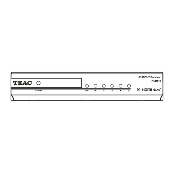
Page 10: Front Panel
WARNING! As this is a High Definition receiver, video output Format should be selected to best match the native resolution of your display. To make initial installation easy, the unit default resolution is 576i which will give a picture on most displays. This can be easily changed. -
Page 11: Rear Panel
3. Rear Panel Composite CVBS video output, RCA VIDEO: Y/C Luminance Chrominance video output, 1 x 4 pin MiniDin S-VIDEO: Component HD video output analogue, 3 x RCA. Y,Pb,Pr: Left and Right channel analogue audio outputs, 2 x RCA. AUDIO L/R: Digital audio output COAXIAL:... -
Page 12: Remote Control
4. Remote Control:... - Page 13 : Switches your receiver between On and Standby. : Mute, switches the sound On or Off. Selects channel by number or inputs numbers to menus. NUMBER KEYS: Switches between the last viewed and current channel. Displays information about the current and next TV program. INFO: Switches between available Audio languages.
-
Page 14: Installing Batteries In Your Remote Control
Note: 1. Colour keys [Red], [Green], [Yellow] and [Blue] operate Teletext functions and some other special functions in Menu. 2. Subtitle and Teletext functions are only available when broadcast. 4.1 Installing Batteries in your Remote Control Remove the battery cover from the remote control. Insert 2 x AAA size batteries inside the battery compartment. -
Page 15: Scan Your Channels
5. Scan your channels Check that ‘Select TV Type’ and ‘Select State’ match your screen shape and location. keys to change selection. Press the [OK] key to start Scan. As digital broadcasts are found each channel is identified on screen and its programs listed. You can cut the scan short by pressing the [OK] or [EXIT] keys. -
Page 16: Menu Structure
III. MENU STRUCTURE 1. Channel When you press the [Menu] key on the Remote Control unit the main Menu engages on screen. Starting from Channel mode, there are 4 sub-menu groups: ‘Channel’, ‘Scan’, ‘Guide’ and ‘Setup’. Channel Mode provides two options: 1) TV Channel List;... - Page 17 1.1.1 Favorite Press the [1] key to select Favorite function. keys Use the to select a Favorite storage location from ‘HD’ ‘SD’ or ‘MOVIES’ etc Use the keys to make a selection. Press the [OK] key and a red mark will show to right side of selected channel name.
- Page 18 1.1.3 Sort Press [3] to engage Sort. Navigate with keys. Programs can be Sorted by ‘Logical’ Channels, ‘Channel Name’ or ‘Frequency’. Press [EXIT] or [MENU] to store. 1.1.4 Add / Delete Press [4] to enter Add / Delete Channel function. keys to select a channel to delete.
-
Page 19: Radio Channel List
1.2 Radio Channel List In ‘Radio Channel List’ you can also select [1] Favorite, [2] Edit, [3] Sort, [4] Add / Delete , [5] Move or [6] Search for channels by following the instructions above for TV Channel List. 2. Channel Scan Channel scan allows you to rescan for all channels. -
Page 20: Manual Scan By Frequency
2.2.1 Manual Scan by Frequency Input desired search frequency by using the numerical keypad on the remote control. Press [OK] to start search. Channel that is found will be saved into channel list. 2.2.2 Manual Scan by Channel Select desired search channel number by keys pressing the Press [OK] to start search. -
Page 21: Setup
Press the [OK] key on the program to add program into “Remind List”. The unit will set a reminder to remind you about the up coming program which are added into the “Remind List”. ‘Simple Guide’ shows abbreviated program information. It is accessed from ‘Full Guide’ by pressing the [Red] key, and vice versa. -
Page 22: System Setting
match method of the receiver’s video output to best match your TV or display (4:3 and 16:9). Screen Format: Select the desired format (Full and Letter). SPDIF Output: Select the desired digital audio output option (Off, PCM and AC3). 4.2 System Setting ‘System Setting’... -
Page 23: System Information
Yellow. Press the ‘OK’ key and receiver will reset. Factory Default password is 1 2 3 4. Use function carefully. Note: This function will reset all settings to default settings and clear all saved channel including favorite list. 4.5 System Information System information provides technical information including Product, Software Version, Hardware Version, and Loader version. -
Page 24: Technical Specification
IV. TECHNICAL SPECIFICATION TUNER Input frequency 174 to 860MHz UHF & VHF Bandwidth 7 or 8 MHz Input level -72 to -20dBm Input impedance 75Ω CHANNEL DECODING Demodulation QPSK,16QAM,64QAM 1/2, 2/3, 3/4, 5/6, 7/8. Mode 8K or 2K Guard Band 1/4, 1/8, 1/16, 1/32 DEMULTIPLEXER Standard... - Page 25 Video output level 1.0V peak to peak Audio output frequency 20Hz to 20KHz Audio output Impedance POWER Input voltage AC100 to 240V, 50 to 60Hz Power consumption 15 W max AMBIENT ° ° C Operating temperature to 40...
-
Page 26: Trouble Shooting
V. TROUBLE SHOOTING Note : If you cannot solve the problem by referring to the above trouble shooting, please contact your local dealer. Problem Possible Causes What To Do The display on the Mains cable is not Check that the main cable is front panel does not connected. - Page 27 For more up to date list please visit our website. Name Address Phone Associated Electronics 7 Molonglo Mall FYSHWICK 2609 (02)62 80 4698 (02)62 80 5437 TEAC Perth Service Centre 30 Hargreaves Street BELMONT 6104 (08)94 79 6499 (08)94 79 6544 Inpulse Electronics 3 Sloane Street MARIBYRNONG 3032...
- Page 28 Inverlec Electronics Shop 1,20 Glen Innes Road INVERELL 2360 (02)67 22 4522 (02)67 22 4522 Maxwell Electronics 106 Bath Road KIRRAWEE 2232 (02)95 42 3000 (02)95 42 3377 Jag Electronics 59 Tambourine Bay Road LANE COVE 2066 (02)94 27 5478 (02)94 28 2634 AVL Electronics 2/87 Bold Street...
- Page 29 Name Address Phone McMahon Electrical Traders 23 Mabel Street ATHERTON 4883 (07)40 91 1788 (07)40 91 1741 Beerwah Electronics Peachester Road BEERWAH 4519 (07)54 94 0466 (07)54 94 0416 Bremer Television Service 36 Station Road BOOVAL 4304 (07)32 82 3593 (07)32 82 1214 De Lacey Electrical Serv (form Bowen) 40 George Street...
- Page 30 Name Address Phone The Television Workshop Shop 4 Elder St Centre ALICE SPRINGS 0870 (08)89 52 8555 (08)89 52 5557 New Age Electronics Unit 1/21 Delatour Street COCONUT GROVE 0810 (08)89 48 1755 (08)89 48 1766 Darwin Electronic Repairs 31 Bishop Street WOOLNER 0820 (08)89 81 0020...
- Page 31 (08)98 81 2148 (08)98 81 3129 Proton 21A Charles Street NORTHAM 6401 (08)96 22 3168 (08)96 22 3168 TEAC Perth Service Centre 273 Great Eastern Highway BELMONT 6104 (08)94 79 6499 (08)94 79 6544 Charles Hunt Electronics 25 Brodie Court...
- Page 32 TEAC CUSTOMER CARE CENTRE (TCCC) Free call: 1800 656 700 Between Monday to Friday – EST 9AM to 5PM...
Need help?
Do you have a question about the HDB841 and is the answer not in the manual?
Questions and answers
My hd receiver saying not support hd on tv screen
The Teac HDB841 HD receiver may display "not support HD" on the TV screen due to an incompatible resolution setting. The receiver supports resolutions such as 1920x1080i, 1280x720p, 720x576p, and 720x576i. If the TV does not support the selected resolution, it may not display the signal correctly. To resolve this, try changing the resolution output of the receiver to a compatible setting using the On Screen Display menu.
This answer is automatically generated