Table of Contents
Advertisement
Advertisement
Table of Contents

Summary of Contents for FarmTrack 675
- Page 1 Kullanım Kılavuzu Farmtrac 675/675DT...
-
Page 2: Table Of Contents
Contents page INTRODUCTION ..........................4 1. GENERAL INFORMATION ......................6 1.1. Identification data.......................... 6 1.2. Safety precautions........................6 1.3. Fire precautions..........................9 1.4. Warranty............................. 10 1.5. Tractor delivery to purchaser....................... 10 2. TECHNICAL SPECIFICATION...................... 12 2.1. - Page 3 5.5. Hydrostatic steering system......................46 5.6. Front axle............................ 46 5.7. Wheels............................49 5.7.1. Front wheel track adjustment....................49 5.7.2. Front wheels toe-in......................49 5.7.3. Rear wheel track adjustment....................50 5.7.4. Tyres use & maintenance....................51 5.7.5.
-
Page 4: Introduction
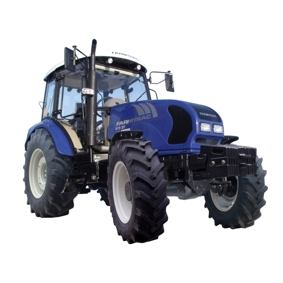
INTRODUCTION This symbol warn of necessity of particularly careful due to possible risk for people and tractor damage. Read this Manual carefully and familiarize yourself with all the controls before attempting to operate the tractor and observe the included rules. Safety symbols Ad. - Page 5 Fig. 1.0. Universal tractor FARMTRAC 675 DT. Thank you for purchasing new Farmtrac tractor. This Manual has been prepared to assist you in the correct procedure for running-in, driving and operating your new tractor and to assist you in the correct method of maintenance to keep it in peak condition.
-
Page 6: General Information
1. GENERAL INFORMATION 1.1. Identification data. Tractor identification data is located on tractor identification plate, located on the right hand side on wall of Cabin under the engine bonnet and affixed with rivets, (Fig. 1a). The plate contains tractor serial number, engine serial number and year of manufacture, etc. ... - Page 7 Operating the tractor Never start the engine while standing beside the tractor. Always sit on the tractor seat. Fasten seat belt and ensure that the Cab/ Roll Over Protective Structure (ROPS) (if fitted) is in place before starting the engine. Apply the parking brake, place the PTO selection lever in the “Neutral”...
- Page 8 7. If the tractor drive wheels are stuck, shift to reverse gear and back out, to prevent from lifting the front wheels off the ground and possibly rolling the tractor over backwards. 8. Slow moving vehicles on highways are dangerous. Use a slow moving (SMV) sign in conjunction with headlights, tail lights and flashing warning lights.
-
Page 9: Fire Precautions
9. The cooling system is operated under pressure which is controlled by the radiator cap. It is dangerous to remove the cap while the system is hot. Allow the engine to cool, then turn the cap slowly to the first stop and allow the pressure to escape before removing the cap entirely. 10. -
Page 10: Warranty
Do not: Modify, drill, weld or alter the CAB/ROPS in any way. Doing so could render you liable to legal prosecution in some counties. Attempt to straighten or weld any part of the CAB/ROPS or retaining brackets which have suffered damage. By doing so you may weaken the structure and endanger you safety. III) Secure any parts on the CAB/ROPS or attach it with other than special high tensile bolts and nuts specified. - Page 11 differential lock, its engagement, disengagement and adjustment, use of power take-off, how to use the hydraulic lift system, attach/detach implements and use of stabilizers. use of external hydraulics, four-wheel drive, its engagement and disengagement, the method of making the wheel track adjustments, front wheel alignment and use of correct tyre pressure, ...
-
Page 12: Technical Specification
2. TECHNICAL SPECIFICATION. Specification / Tractor model FT 675 DT FT 675 2.1. Engine. Engine model PERKINS 1104D-44T 3061/2200 Engine type four stroke, water-cooled, turbocharged, direct injection diesel Number of cylinders 4, vertical, in-line 1 – 3 – 4 - 2... -
Page 13: Electrical System
Cooling System Type Pressurised recirculation, by pass with radiator, fan, thermostat Cooling system capacity, litres 17 dm 10 blades, diameter 457 mm 13 19 mm Fan / alternator belt deflection, mm Recommended coolant see coolant specification Air cleaner Type dry type, two-stage, in front of radiator 2.2. - Page 14 Ratios and tractor ground speeds Table 1. Total ratio Theoretical tractor ground speeds in km/h at engine rated speed for specified tyre size / effective rolling circuit For- Back- 18,4-30 / 4522 16,9-30 / 4365 16.9-28 / 4280 16,9R30 / 4317 18,4-R30 / 4537 270/95R38 /4457 ward...
-
Page 15: Hydraulic Lift System
Ground PTO shaft revolutions No. for specified tyre size used Tyre size 16.9-28 16.9-30 16.9 R 30 18.4-30 18.4 R 30 270/95 R 38 Ground PTO 2,8278 2,7525 2,8035 2,6180 2,6676 2,7155 shaft rotations 1000 for 1 km distance 5,1729 5,0352 5,1285 4,7891... -
Page 16: Wheels & Axles
2.8. Wheels & axles. Front axle type type rigid, swivel pin mounted, driven rigid, swivel pin mounted, not driven Spindles rigid, extendable, type wheel track adjustable Rear wheels: W 16L x 30 W 15L x 30 Rim size ... -
Page 17: Tractor Weight
2.10. Tractor weight. Weight of tractor in running order, kg 3585 kg 3308 kg Weight distribution on axle, kg: front 1470 kg 1204 kg rear 2115 kg 2104 kg 6000 kg Maximum permissible tractor weight kg Weight distribution on axle kg: ... -
Page 18: Instrument Panel & Control Devices
3. INSTRUMENT PANEL & CONTROL DEVICES 3.1. Instrument Panel. The following text describes the various gauges, switches, warning lights and control levers situated on the instrument panel, or close to it (Fig 3.1). Coolant temperature gauge (1) The gauge indicates the temperature of the engine coolant. If the pointer enters the red zone of the gauge while the engine is running, stop the engine and investigate the cause. - Page 19 Key-start switch (8) Positions of the key: Pos. 1 – OFF, Pos. 2 – (key turned clockwise 30) – electrical accessories ON, Pos. 3 – (key turned clockwise 60) – flame plug is energized for cold weather starting, (spring turns the key automatically to pos.
-
Page 20: Control Levers And Pedal
Dipped (lower) beam warning light (22) – green This warning light illuminates when the headlights are switched to dipped (lower) beam. Steering wheel adjustment lever (23) The lever is used to adjust the steering wheel tilt and is always in the permanent lock position. To change the steering wheel tilt, move the wheel lock lever downwards and set the steering wheel to the desired position. - Page 21 PTO selector lever (7) This lever has three positions as shown on the decal situated by the lever: upper position – engine speed PTO engaged, centre position – neutral, bottom position – ground speed PTO engaged. When moving the lever to the upper position, always disengage the PTO clutch by means of a lever (6).
- Page 22 Position of gear selection levers. Shuttle lever Range lever Main gear lever Shuttle lever (24-Fig. 3.1) The shift pattern is given on the top of the lever knob. The lever has three positions: Forwards, Centre Neutral, Rearwards. WARNING: 1.
-
Page 23: Tractor Cab
Parking brake lever (20) Parking brake is used to lock the tractor rear wheels for parking and/or stationary operation. To engage the parking brake, latch the service brakes together and press them down. Then pull the hand lever up. To release the parking brake, press the service brake pedals down, then press the button on the end of the lever and push the lever down. -
Page 24: Operator's Seat Adjustments
Fig. 3.3 Tractor cab. Switches in the cab roof blower switch (5) – this used to switch on/off the fresh air blow into the cab through the vents in the cab roof (11), rear window wiper switch (6), ... -
Page 25: Operation
4. OPERATION. 4.1. Tractor running in. Your new tractor will provide long and dependable service if given proper care during the first 50 hours running in period and if serviced at the recommended intervals. Therefore, the following precaution should be taken during the running-in period: ... - Page 26 WARNING: Do not leave this lever in operating position, front or reverse, if not needed, otherwise the hydraulic pump may get damaged. Start the tractor only from the operator’s seat WARNING: Starting the engine Normal starting procedure (at the ambient temperatures above 5C) To start the engine, proceed as follows: ...
-
Page 27: Driving The Tractor
4.3. Driving the tractor. After starting the engine: depress the clutch pedal, then select the desired speed range, gear and direction gear, release the parking brake lever, increase the engine speed slowly and simultaneously release the clutch pedal slowly, ... -
Page 28: Power Take-Off (Pto)
When attaching a trailer, or trailed machines to the tractor, ensure that the trailer air braking system is connected. To connect the trailer braking system to the tractor braking system, proceed as follows: engage the parking brake (this will cause the air pressure in the hose drop down to the atmospheric pressure, ... - Page 29 WARNING: Before operating the tractor with PTO driven implements, familiarize yourself with the safety precautions given below and strictly observe them: 1. Before connecting, disconnecting, cleaning or adjusting the PTO driven implements, disengage the PTO drive, stop the engine, remove the key, apply the hand brake and make sure that the PTO drive line has stopped.
-
Page 30: Tractor Hydraulic System
WARNING: Keep the PTO shaft in engage position (PTO clutch lever fully lowered) irrespectively of the PTO selector lever. Before select PTO speed pull the PTO clutch lever fully. To select PTO speed move the PTO selector lever (7– Fig. 3.2). There are three positions as shown on sticker beside the lever: 1 - independent PTO engaged Independent... - Page 31 Flow Control knob 15. The Position and Draft Control levers are used in conjunction to raise or lower the three-point linkage (and implement) to the required height and adjust the working depth. In order to operate the three-point linkage, the external hydraulics control lever must be kept in neutral position.
-
Page 32: External Hydraulics Control
The hydraulic lift system will now provide normal draft response within the range set by the position control. This adjustment provides a more uniform depth while maintaining an even pull in widely varying soil conditions. Flow and sensitivity control (fig. 3.2) Your tractor is equipped with hydraulic Flow and Sensitivity Control mechanism., operated by two knobs provided on the platform area. -
Page 33: Equipment Attaching On Three-Point Linkage
WARNING: Do not leave the joystick in its front lock position unless needed, to avoid hydraulic pump damage. WARNING: Leaking fluid under pressure can penetrate the skin causing serious injury. Avoid the hazard by relieving pressure before disconnecting hydraulic lines. Tighten all connections before applying pressure. - Page 34 Attaching implement to the three-point linkage shift the upper transport hitch to top position (1 - Fig. 4.6.2), remove the upper transport hitch (1 - Fig. 4.6), remove the drawbar (7 - Fig. 4.6.2) after putting out pins (9 - Fig. 4.6.2), ...
- Page 35 To detach, reverse the procedure of attaching. Apart from the three-point hitch (Fig D8), the machines and implements can be attached to: upper transport hitch (for 2-axle trailers), linkage drawbar, lower transport hitch (for single-axle trailer), multi-hole drawbar.
-
Page 36: Attaching Trailed Machines And Implements
4.7. Attaching trailed machines and implements. Apart from the three-point hitch (Fig 4.6.1), the machines and implements can be attached to: upper transport hitch, tractor drawbar, lower transportation hitch, multi-hole drawbar. Upper transport hitch (Fig 1 - 4.6.2), – is used for hitching a two-axle trailers. This hitch must be detached when attaching implements to the three-point hitch. -
Page 37: Maintenance And Adjustment
5. MAINTENANCE AND ADJUSTMENT 5.1. Periodic maintenance chart. Table 4 Hours of Service requirements operation Engine oil level Every 10 Dry air cleaner dust collector Hours Radiator coolant level Radiator matrix and oil cooler Water in air reservoir (if fitted) Air compressor V-belt (during first 30 hours) Dry air cleaner outer element First 50... - Page 38 Hours of Service requirements operation Dry air cleaner outer element Every 150 Hours Oil level in hydrostatic steering oil reservoir Transmission and rear axle oil level Front drive axle oil including final reduction units Air compressor (if fitted) and fan V-belts tension) Lubrication acc.
-
Page 39: Lubrication
5.2. Lubrication. 5.2.1. Oils. Following lubricating grades of oil are applicable in Farmtrac tractors: Table 5 Oil kind Recommended oil grade Application Oil level TEXACO Super Universal Engine oil Oil sump Between marks on Tractor Oil 15W-30 dipstick Rear axle Transmission oil TEXACO Super Universal Between marks on Tractor Oil 15W-30... -
Page 40: Engine
5.3. Engine. 5.3.1. Engine lubrication system. Engine oil and filter change Check the engine oil level every 10 hours of operation, or daily. Before checking the oil level, stop the engine and wait for a short period to allow the oil to drain back into the sump (tractor must be on level ground). -
Page 41: Dry Air Cleaner
To remove water and impurities from the fuel filter, loosen the drain plugs (3 - Fig. 5.3.4) at the bottom of the fuel filter to allow the water/fuel to drain into a suitable container. Additionally tractor is fitted with fuel separator (7-Fig. 5.3.4). Drain the separator when water and impurities accumulates inside by loosing the drain plugs (3 - Fig. -
Page 42: Cooling System
alternatively, compressed air not exceeding 2 kg/cm² may be used. Insert the air line nozzle inside the element and blow the dust from the inside to the outside. Keep the nozzle at a safe distance from the element. Blow loose particles from the outside of the element by holding the nozzle at least 150 mm from the element, ... -
Page 43: Electrical System
Cylinder and valve number Valve I = Inlet E = Exhaust NOTE: No. 1 cylinder is at the front of engine. if adjustment is needed: - loosen the lock nut and adjust the clearance by turning the adjusting screw on the valve rocker, - retighten the lock nut while keeping the adjusting screw in position, - recheck the valve clearance, ... -
Page 44: Alternator Maintenance
Fig. 5.4. V-belts. 1-Compressor V-belt. 2 - Alternator V-belt. 3 - Compressor. 4 - Alternator. 5 - Fan protection cover.. 6- Fan V-belt. 5.4.1 Alternator maintenance. Check the fan/alternator V-belt tension every 150 hours of operation. (Fig. 5.4). The correct belt deflection is 8 mm, with the belt depressed (with a force of about 25N). If adjustment is required: ... -
Page 45: Spot Lights Adjustment
WARNING: 1. During servicing be utmost careful when in contact with sulphuric acid (pour acid into water) to prevent contamination of the body, clothing or other objects. If such contamination occurs, immediately flush the contaminated spot with water liberally and neutralize with 2,5% solution of borax and water. The electrolyte should be prepared using protective clothing and glasses. -
Page 46: Hydrostatic Steering System
Table 9 Application Bulb indication Nos. per tractor Headlights (main and dipped beam) H4 12V 60/55 W Front and rear work lamps H3 12V 55W Front marker lights 12V 5W Rear marker lights and stop lights 12V 5/21W Flashing indicators (front and rear) 12V 21W Number plate illumination 12V 5W... - Page 47 Front wheel bearings adjustment Inspect the front wheel bearings clearance every 600 hours of operation at raised axle and freely rotating wheel. If there is found excessive axial clearance at the wheel, adjust it as follows: unscrew the hub cup; - Remove the castellated nut securing pin;...
- Page 48 Fig. 5.6.5. Front non-driven axle Fig. 5.6.6. Epicyclical reduction unit of 1- Track rod ball joint clamp. 2- Ball joint bolt front drive axle. 3- Track adjustment bolts. 4- Center sleeve retaining bolts. 1- Filler / level plug, 5- Track rod ball joint. 2- Oil level line in wheel hub.
-
Page 49: Wheels
5.7. Wheels. 5.7.1. Front wheel track adjustment. Non driven front axle Front extension axles enable to set front wheel track in range of 1230 1930 mm. To adjust the front wheel track, proceed as follows: apply the parking brake, ... -
Page 50: Rear Wheel Track Adjustment
To adjust non-driven front axle To adjust non-driven axle toe-in (Fig. 5.6.5 and Fig. 5.7.3) : remove the R.H. side track rod end 5 from the steering arm and loosen the clamp bolt 1, screw in or out the track rod ball joint as desired, ... -
Page 51: Tyres Use & Maintenance
1508 mm 1702 mm 1795 mm 1908 mm 1305 mm 1395 mm 1592 mm Fig. 5.7.5 Rear wheel track 5.7.4. Tyres use & maintenance. Check tyre inflation pressure every 10 hours of operation or daily before starting work. WARNING: These rules, if followed carefully, will ensure maximum tyre life: ... -
Page 52: Clutch
5.8. Clutch. Every 150 hours of operation grease: a) with grease, clutch linkage pedal pivot (1-Fig. 5.8.1), reverse pivot shaft (Fig. 5.8.2), reverse pivot sleeves (Fig. 5.8.3) – upper sleeve is accessible after opened tractor bonnet and lower sleeve is accessible after removed steering column LHS cover b) with grease-maintaining agent - clutch linkage attachment pivot in clutch pedal lever fork. -
Page 53: Transmission & Rear Axle Maintenance
NOTE: Adjust the transmission clutch pedal free travel before adjusting the PTO clutch. Keep the PTO clutch always in engaged condition, that is lever in down position irrespective of whether the PTO is in use or not. 5.9. Transmission & rear axle maintenance. Every 150 hours of operation check and replenish if necessary transmission &... -
Page 54: Braking System
clean the filter element by blowing on the filter element with compressed air at a pressure not exceeding 0,7 MPa and keeping the nozzle at a reasonable distance from the element. The air stream should be directed opposite to this of air flow in normal operation, ... -
Page 55: Parking Brake
5.12.2. Parking brake. Parking brake adjustment should follow the service brake adjustment. If correctly adjusted, the parking brake should act securely, when the ratchet pawl is snapped in the third to fifth recess on the rack, counting from the lowest position. Adjust the parking brake as follows: ... - Page 56 New belt will “bed in” and may require adjustment after ten hours service. Check the tension of a new belt every 10 hours or daily within first 30 hours of operation. The correct belt deflection is 8 mm. If adjustment is required: ...
- Page 57 Any kind of the air reservoir repair is not permitted Drain water from the air reservoir every 10 hours of operation or daily by pushing drain valve at bottom of the reservoir. Pressure regulating valve with safety valve The pressure is compressed to the air container through the valve. The valve reduces the air pressure ±0,02 ±00,4 and Δp...
-
Page 58: Hydraulic Lift
5.14. Hydraulic lift. Hydraulic lift is supplied with oil from tractor transmission system. Grease lift rocker solid grease. Bleeding Hydraulic lift system: - check transmission system oil level before bleeding, replenish if required, - start the engine, move slowly distributor lever from “raising” to “lowering” position – without loading three point linkage, don’t load hydraulic lift with implements for several minutes. -
Page 59: Engine Fault Finding Chart
6. ENGINE FAULT FINDING CHART The following are suggestions listed for your convenience. You can make simple adjustments on you tractor that will improve its operation and save your time. If any trouble is experienced, make sure of the cause before attempting to make any adjustments. Always make one adjustment at a time, and if the adjustment made does not improve the problem, return to the original setting before proceeding to the next adjustment. - Page 60 17 - Incorrect type or grade of fuel. 47 - Lubricating oil pump worn. 18 - Restricted movement of engine speed 48 - Relief valve sticking open. control. 49 - Relief valve sticking closed. 19 - Restriction in exhaust pipe. 50 - Relief valve spring broken.
-
Page 61: Tractor Storage
7. TRACTOR STORAGE If your tractor is to be out of service of any length of time, certain precautionary measures must be taken to safeguard it. It is recommended, if the standstill period is not very long, to run the engine every 7 days until the operating temperature of the engine is reached (green scale in the water temperature gauge). -
Page 62: Wiring Diagrams
8. WIRING DIAGRAMS FT 675 WIRING DIAGRAM (without cab) - Page 63 KEY TO FT675 WIRING DIAGRAMS 1. Battery. 31. Windscreen washer motor. 2. Alternator. 32. Windscreen washer switch. 3. Starter motor. 33. Windscreen wiper motor. 4. Earth switch. 34. Windscreen wiper switch. 5. Safety start switch. 35. Master switch. 6. Coolant temperature sender unit. 36.
- Page 64 CAB WIRING DIAGRAM KEY TO CAB WIRING DIAGRAM: 1 - Front work lamps. 9 - Cab lighting lamp. 2 - Rear work lamps. 10 - Illumination lamps of switches. 3 - Front work lamps switch. 11 - Rear window wiper switch. 4 - Rely of front work lamps switch.
Need help?
Do you have a question about the 675 and is the answer not in the manual?
Questions and answers