Table of Contents
Advertisement
Quick Links
P.O. BOX 265
OGDENSBURG, NY
U.S.A. 13669-0265
A V T E C H
TEL: 888-670-8729 (USA & Canada) or +1-613-686-6675 (Intl)
FAX: 800-561-1970 (USA & Canada) or +1-613-686-6679 (Intl)
info@avtechpulse.com
INSTRUCTIONS
MODEL AV-1030-B
0 TO ±5 VOLTS, 10 MHz
GENERAL PURPOSE LAB PULSE GENERATOR
WITH 300 ps RISE TIMES
AND IEEE 488.2, RS-232 CONTROL
SERIAL NUMBER: ____________
E L E C T R O S Y S T E M S
N A N O S E C O N D
W A V E F O R M
S I N C E
-
http://www.avtechpulse.com/
E L E C T R O N I C S
1 9 7 5
BOX 5120, LCD MERIVALE
X
OTTAWA, ONTARIO
CANADA
L T D .
K2C 3H4
Advertisement
Table of Contents

Related Manuals for Avtech AV-1030-B


Summary of Contents for Avtech AV-1030-B
- Page 1 FAX: 800-561-1970 (USA & Canada) or +1-613-686-6679 (Intl) OTTAWA, ONTARIO U.S.A. 13669-0265 CANADA K2C 3H4 info@avtechpulse.com http://www.avtechpulse.com/ INSTRUCTIONS MODEL AV-1030-B 0 TO ±5 VOLTS, 10 MHz GENERAL PURPOSE LAB PULSE GENERATOR WITH 300 ps RISE TIMES AND IEEE 488.2, RS-232 CONTROL SERIAL NUMBER: ____________...
-
Page 2: Warranty
Avtech product is found to be defective, Avtech shall at its option repair or replace said defective item. This warranty does not apply to units which have been dissembled, modified or subjected to conditions exceeding the applicable specifications or ratings. -
Page 3: Table Of Contents
TABLE OF CONTENTS WARRANTY........................2 TECHNICAL SUPPORT....................2 TABLE OF CONTENTS....................3 INTRODUCTION.......................5 SPECIFICATIONS......................6 REGULATORY NOTES....................7 FCC PART 18.......................... 7 EC DECLARATION OF CONFORMITY..................7 DIRECTIVE 2002/95/EC (RoHS).....................8 DIRECTIVE 2002/96/EC (WEEE)....................8 AC POWER SUPPLY REGULATORY NOTES...............9 INSTALLATION......................10 VISUAL CHECK........................10 POWER RATINGS........................10 CONNECTION TO THE POWER SUPPLY................10 PROTECTION FROM ELECTRIC SHOCK................11 ENVIRONMENTAL CONDITIONS..................12 LABVIEW DRIVERS......................12... - Page 4 PCB 104E - KEYPAD / DISPLAY BOARD, 1/3..............38 PCB 104E - KEYPAD / DISPLAY BOARD, 2/3..............39 PCB 104E - KEYPAD / DISPLAY BOARD, 3/3..............40 MAIN WIRING........................41 PERFORMANCE CHECK SHEET.................42 Manual Reference: /fileserver2/officefiles/instructword/av-1030/av-1030-b,edition6.odt. Last modified May 14, 2012. Copyright © 2012 Avtech Electrosystems Ltd, All Rights Reserved.
-
Page 5: Introduction
It also features an exceptionally fast 300 ps rise and 350 ps fall times. The AV-1030-B is a highly flexible instrument. Aside from the internal trigger source, it can also be triggered or gated by external TTL-level signals. A front-panel pushbutton or a computer command can also be used to trigger the instrument. -
Page 6: Specifications
SPECIFICATIONS Model: AV-1030-B GPIB and RS-232 control: Amplitude (to 50 Ohms) 0 to ±5 Volts Output impedance: 50 Ohms Rise time (20%-80%): ≤ 300 ps Fall time (80%-20%): ≤ 350 ps Pulse repetition frequency (PRF): 1 Hz to 10 MHz... -
Page 7: Regulatory Notes
If interference is observed, check that appropriate well-shielded cabling is used on the output connectors. Contact Avtech (info@avtechpulse.com) for advice if you are unsure of the most appropriate cabling. Also, check that your load is adequately shielded. It may be necessary to enclose the load in a metal enclosure. -
Page 8: Directive 2002/95/Ec (Rohs)
Directive 2002/96/EC categories 1-7 and 10, as stated in the "Article 2 - Scope" section of Directive 2002/95/EC. DIRECTIVE 2002/96/EC (WEEE) European customers who have purchased this equipment directly from Avtech will have completed a “WEEE Responsibility Agreement” form, accepting responsibility for WEEE compliance (as mandated in Directive 2002/96/EC of the European Union and local laws) on behalf of the customer, as provided for under Article 9 of Directive 2002/96/EC. -
Page 9: Ac Power Supply Regulatory Notes
AC POWER SUPPLY REGULATORY NOTES This instrument converts the AC input power to the +24V DC voltage that powers the internal circuitry of this instrument using a Tamura AAD130SD-60-A switching power supply. According to the manufacturer, the Tamura AAD130SD-60-A has the following certifications: UL60950-1 IEC60950 -1... -
Page 10: Installation
INSTALLATION VISUAL CHECK After unpacking the instrument, examine to ensure that it has not been damaged in shipment. Visually inspect all connectors, knobs, liquid crystal displays (LCDs), and the handles. Confirm that a power cord, a GPIB cable, and two instrumentation manuals (this manual and the “Programming Manual for -B Instruments”) are with the instrument. -
Page 11: Protection From Electric Shock
5. Do not attempt any repairs on the instrument, beyond the fuse replacement procedures described in this manual. Contact Avtech technical support (see page 2 for contact information) if the instrument requires servicing. Service is to... -
Page 12: Environmental Conditions
6. no pollution or only dry, non-conductive pollution. LABVIEW DRIVERS A LabVIEW driver for this instrument is available for download on the Avtech web site, at http://www.avtechpulse.com/labview. A copy is also available in National Instruments' Instrument Driver Library at http://www.natinst.com/. -
Page 13: Fuses
FUSES This instrument contains four fuses. All are accessible from the rear-panel. Two protect the AC prime power input, and two protect the internal DC power supplies. The locations of the fuses on the rear panel are shown in the figure below: Fuses #1 and #2 Fuse #4 Fuse #3... -
Page 14: Dc Fuse Replacement
DC FUSE REPLACEMENT The DC fuses may be replaced by inserting the tip of a flat-head screwdriver into the fuse holder slot, and rotating the slot counter-clockwise. The fuse and its carrier will then pop out. FUSE RATINGS The following table lists the required fuses: Recommended Replacement Part Nominal Fuses... -
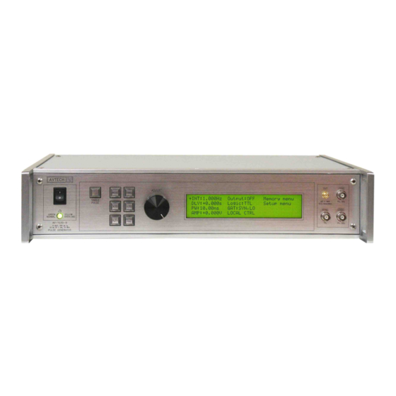
Page 15: Front Panel Controls
FRONT PANEL CONTROLS 1. POWER Switch . This is the main power switch. When turning the instrument on, there may be a delay of several seconds before the instrument appears to respond. 2. OVERLOAD Indicator . When the instrument is powered, this indicator is normally green, indicating normal operation. - Page 16 reversed. 7. LIQUID CRYSTAL DISPLAY (LCD) . This LCD is used in conjunction with the keypad to change the instrument settings. Normally, the main menu is displayed, which lists the key adjustable parameters and their current values. The “Programming Manual for -B Instruments” describes the menus and submenus in detail.
-
Page 17: Rear Panel Controls
REAR PANEL CONTROLS GATE TRIG RS-232 GPIB 1. AC POWER INPUT . An IEC-320 C14 three-pronged recessed male socket is provided on the back panel for AC power connection to the instrument. One end of the detachable power cord that is supplied with the instrument plugs into this socket. - Page 18 See the “Programming Manual for -B Instruments” for more details on RS-232 control. 8. AMP Connector . This connector is not used on the AV-1030-B. If any additional items are present, they are unused or inactive.
-
Page 19: General Information
GENERAL INFORMATION BASIC PULSE CONTROL This instrument can be triggered by its own internal clock or by an external TTL trigger signal. In either case, four output channels respond to the trigger: OUT, SYNC, LOGIC, and LOGIC-Complement. • OUT. This is the main output. The pulse width and amplitude are adjustable. The maximum output voltage is ±5V. - Page 20 If the delay is negative, the order of the SYNC and OUT pulses is reversed: 50 ns, FIXED SYNC OUT (generated by the 3V, FIXED internal oscillator) DELAY < 0 PULSE WIDTH AMPLITUDE, VARIABLE MAIN OUTPUT +5V (TTL) or -0.8V (ECL) LOGIC OUTPUT 0V (TTL) or -1.6V (ECL) +5V (TTL) or -0.8V (ECL)
- Page 21 > 4 ns TRIG TTL LEVELS (external input) (0V and 3V-5V) PROPAGATION DELAY (FIXED) 50 ns, FIXED SYNC OUT 3V, FIXED DELAY > 0 PULSE WIDTH AMPLITUDE, VARIABLE MAIN OUTPUT +5V (TTL) or -0.8V (ECL) LOGIC OUTPUT 0V (TTL) or -1.6V (ECL) +5V (TTL) or -0.8V (ECL) LOGIC OUTPUT 0V (TTL) or -1.6V (ECL)
-
Page 22: Trigger Modes
TRIG TTL LEVELS (external input) (0V and 3V-5V) PROPAGATION DELAY (FIXED) ≈ PW AMPLITUDE, VARIABLE MAIN OUTPUT +5V (TTL) or -0.8V (ECL) LOGIC OUTPUT 0V (TTL) or -1.6V (ECL) +5V (TTL) or -0.8V (ECL) LOGIC OUTPUT 0V (TTL) or -1.6V (ECL) The delay, pulse width, and frequency (when in the internal mode), of the OUT pulse can be varied with front panel controls or via the GPIB or RS-232 computer interfaces. -
Page 23: Pulse Width Modes
PULSE WIDTH MODES This instrument has two pulse width modes: • Normal: the instrument controls the output pulse width. • PW : the output pulse width equals the pulse width of the trigger signal on the “TRIG” connector. The instrument must be in the external trigger mode. These modes can be selected using the front panel pulse width menu, or by using the appropriate programming commands. -
Page 24: Minimizing Waveform Distortions
MINIMIZING WAVEFORM DISTORTIONS USE 50 OHM TRANSMISSION LINES AND LOADS Connect the load to the pulse generator with 50Ω transmission lines (e.g. RG-58 or RG-174 cable). This instrument requires a 50Ω load for proper operation. It will not properly drive a high-impedance load. -
Page 25: Typical Waveforms
TYPICAL WAVEFORMS The following waveform photo shows the rising and falling edges of the main output with the AV-1030-B set to 100 kHz repetition rate, 100 ns pulse width, +5V amplitude, into a 50 Ohm load: Top: Rising edge Bottom: Falling edge Both: 2 V/div (i.e., 20 mV/div... -
Page 26: Operational Check
Then read the “Local Control” section of the “Programming Manual for -B Instruments” thoroughly. The “Local Control” section describes the front panel controls used in this operational check - in particular, the MOVE, CHANGE, and ADJUST controls. SAMPLING AVTECH OSCILLOSCOPE PULSER BW > 5 GHz MAIN OUTPUT... - Page 27 2.Turn on the AV-1030-B. The main menu will appear on the LCD. 3.To set the AV-1030-B to trigger from the internal clock at a PRF of 10 kHz: a)The arrow pointer should be pointing at the frequency menu item. If it is not, press the MOVE button until it is.
- Page 28 a)Press the MOVE button until the arrow pointer is pointing at the output menu item. b)Press the CHANGE button. The output submenu will appear. c)Press MOVE until the arrow pointer is pointing at the “ON” choice. d)Press CHANGE to return to the main menu. 8.To change the output amplitude: a)Press the MOVE button until the arrow pointer is pointing at the amplitude menu item.
-
Page 29: Programming Your Pulse Generator
PROGRAMMING YOUR PULSE GENERATOR KEY PROGRAMMING COMMANDS The “Programming Manual for -B Instruments” describes in detail how to connect the pulse generator to your computer, and the programming commands themselves. A large number of commands are available; however, normally you will only need a few of these. -
Page 30: All Programming Commands
In the above example, the pulse width of the output was set by a programming command. To set the output pulse width to track the trigger pulse width in external mode, use: *rst (resets the instrument) trigger:source external (selects internal triggering) pulse:width in = PW output:type TTL... - Page 31 [:IMMediate] [:AMPLitude] <numeric value> :PROTection :TRIPped? [query only] STATUS: :OPERation :[EVENt]? [query only, always returns "0"] :CONDition? [query only, always returns "0"] :ENABle <numeric value> [implemented but not useful] :QUEStionable :[EVENt]? [query only, always returns "0"] :CONDition? [query only, always returns "0"] :ENABle <numeric value>...
-
Page 32: Mechanical Information
There are no user-adjustable internal circuits. For repairs other than fuse replacement, please contact Avtech (info@avtechpulse.com) to arrange for the instrument to be returned to the factory for repair. Service is to be performed solely by qualified service personnel. -
Page 33: Maintenance
MAINTENANCE REGULAR MAINTENANCE This instrument does not require any regular maintenance. On occasion, one or more of the four rear-panel fuses may require replacement. All fuses can be accessed from the rear panel. See the “FUSES” section for details. CLEANING If desired, the interior of the instrument may be cleaned using compressed air to dislodge any accumulated dust. -
Page 34: Wiring Diagrams
WIRING DIAGRAMS WIRING OF AC POWER M a in s c ir c u i ts - h a z a r d o u s liv e . D o n o t a tte m p t a n y r e p a i r s o n th is in s t r u m e n t b e y o n d t h e fu s e r e p l a c e m e n t p r o c e d u r e s d e s c r i b e d in th e m a n u a l . -
Page 35: Pcb 158N - Low Voltage Power Supply, 1/3
PCB 158N - LOW VOLTAGE POWER SUPPLY, 1/3 p c b 1 5 8 N _ o v p p c b 1 5 8 N _ o v p . s c h + 1 5 V + 1 5 V + 1 5 V B U + B U +... -
Page 36: Pcb 158N - Low Voltage Power Supply, 2/3
PCB 158N - LOW VOLTAGE POWER SUPPLY, 2/3 8 3 0 8 3 5 F U S E H O L D E R 6 4 0 4 4 5 - 6 T P 6 T P 3 T E S T - L O O P T E S T - L O O P S 1 A S 1 B , O R D C... -
Page 37: Pcb 158N - Low Voltage Power Supply, 3/3
PCB 158N - LOW VOLTAGE POWER SUPPLY, 3/3 R 2 1 1 . 5 K o r 1 . 8 K O Y C A P B A N K R 2 6 1 5 K C 2 3 1 0 0 0 u F , 3 5 V ( P 5 1 6 9 - N D ) L 6 2 7 1 1 H V W A R N I N G R 1 7... -
Page 38: Pcb 104E - Keypad / Display Board, 1/3
PCB 104E - KEYPAD / DISPLAY BOARD, 1/3 A H E 1 0 G - N D , M f g 4 9 9 9 1 0 - 1 , 1 0 p i n s t r a i g h t h e a d e r L C D - B U T T L C D - B U T T . -
Page 39: Pcb 104E - Keypad / Display Board, 2/3
PCB 104E - KEYPAD / DISPLAY BOARD, 2/3 U 4 A V C C C 1 0 V C C B U T 1 V C C 2 . 2 u F C 1 5 C 1 3 1 5 K V C C M M 7 4 H C 1 4 N 0 . -
Page 40: Pcb 104E - Keypad / Display Board, 3/3
PCB 104E - KEYPAD / DISPLAY BOARD, 3/3 V C C V C C 0 . 1 u F 2 . 2 u F G N D V C C V C C V C C S D A S D A S C L S C L I N T... -
Page 41: Main Wiring
MAIN WIRING - T N T O P T I O N O N L Y C O N N 2 V C C L E D M O U N T L - C O M E C F 5 0 4 - S C 5 L - C O M T R D 8 5 5 S I G - 1 C A B L E A M B G R N... -
Page 42: Performance Check Sheet
PERFORMANCE CHECK SHEET...
Need help?
Do you have a question about the AV-1030-B and is the answer not in the manual?
Questions and answers