
Summary of Contents for mensor DPG 2400
- Page 1 Operating Instructions Digital Pressure Gauge DPG 2400 Digital Pressure Gauge DPG 2400 Series PN 0017460001R • 07/2013...
- Page 2 This Caution symbol indicates danger for the system and material if the respective safety precautions are not taken. Caution This Notice symbol does not indicate safety notices but information for a better understanding of the facts. Operating Instructions DPG 2400 Series...
-
Page 3: Table Of Contents
5.4 Electrical Connections 5.5 Power On 6. Local Operation 6.1 Keypad 6.2 Standard Display 6.3 Menu Screens 6.3.1 Main Menu Screen 6.3.2 Password Entry Screen 6.3.3 Sensor Calibration Screen 6.3.4 Pressure Units Screens 6.4 Menu Tree Operating Instructions DPG 2400 Series... - Page 4 7.2.5 Commands and Queries 7.2.6 User Programmable Pressure Units 7.2.7 Pressure Units Codes and Conversions 8. Calibration 8.1 Environment 8.2 Equipment 8.3 Pressure Standard 8.4 Calibration Medium 8.5 Calibration Process 8.5.1 Zero Adjustment 8.5.2 Span Adjustment Operating Instructions DPG 2400 Series...
-
Page 5: General Information
Mensor, this warranty does not apply. The judgment of Mensor will be final as to all matters concerning condition of the product, the cause and nature of a defect, and the necessity or manner of repair. -
Page 6: Software License Agreement
1.4 Mensor Service Plus If you have problems and you don’t find the answer in this manual, contact Mensor at 1.800.984.4200 (USA only) or 1.512.396.4200 for personal assistance, or at any of the contact addresses listed on the rear cover of this manual. -
Page 7: Safety Notices
Caution CAUTION: Avoid excessive overpressure to the sensor! Externally mounted relief valves to provide overpressure protection are available from Mensor as optional devices. Caution CAUTION: Use of a power supply other than the one provided by Mensor will invalidate the warranty. - Page 8 Digital Pressure Gauge DPG 2400 Series Notes Operating Instructions DPG 2400 Series...
-
Page 9: Product Description
VDC @ 830 mA max. 3.4 Serial In/Out Communications The serial port can be used to configure and calibrate the DPG 2400, or to read the out- put of its sensor. Depending on how your DPG 2400 was ordered, the instrument came with either RS-232 or RS-485 serial port communications. - Page 10 100 ft. Wiring requirements are provided in Section 5.4, “Electrical Connections”, and a list of valid commands and responses is provided in Section 7.2.5, “Commands and Queries”. Operating Instructions DPG 2400 Series...
-
Page 11: Specifications
National Institute of Standards and Technology (NIST). These specifications are obtained in accordance with the ISO Guide to the Expression of Uncertainty in Measurement (GUM). The calibration program at Mensor is accredited by the American Association of Laboratory Accreditation (A2LA) as complying with both the ISO/IEC 17025:2005 and the ANSI/NCSL Z540-1-1994 standards. - Page 12 Pressure Units See Table 7.2.7, “Pressure Units Codes and Conversions”. Display Monochrome 128 x64 LCD with white LED backlight. Compliance The DPG 2400 is compliant to the following CE Standards: EN 50081 and EN 50082. Operating Instructions DPG 2400 Series...
-
Page 13: Installation
Upon receipt, please examine the transducer for shipping damage. Report any apparent damage to the carrier immediately. In addition to this manual you should have: • One DPG 2400 Digital Pressure Gauge; • Power adapter; • Any accessories ordered;... -
Page 14: Dimensions
Digital Pressure Gauge DPG 2400 Series 5.2 Dimensions Figure 5.2 - Case Outline/Dimensions Operating Instructions DPG 2400 Series... -
Page 15: Pressure Connections
DPG 2400 Series 5.3 Pressure Connections The 7/16-20 SAE female NPT threaded port is the pressure input of the DPG 2400. If the sensor range is less than 20 psi and is a gauge or bi-directional sensor, there will also be a 1/16 inch hose barb fitting above the pressure port. The barb fitting provides access to the reference port of the sensor. -
Page 16: Electrical Connections
DPG 2400 Series 5.4 Electrical Connections For RS-232 serial port operation, connect the DPG 2400 to the host computer per Figure 5.4a. Notice that the host TRANSMIT line is connected to the DPG 2400 RECEIVE line (TX to RX), and vice versa. -
Page 17: Local Operation
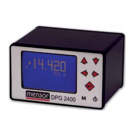
The ( ) key is the power on/off switch. Figure 6.1 - Keypad and Display Features 6.2 Standard Display When the DPG 2400 is powered on, a pressure reading will be displayed after the initialization screen. Figure 6.2 - Display Screen (standard) -
Page 18: Menu Screens
The instrument will con- tinuously update the peaks until “Peak Rst” is selected. Peak Reset: Resets the peak values to the current measured pressure. A Setup Peak On Peak Rst Null Off Units Sensor A Operating Instructions DPG 2400 Series... - Page 19 “Null Off”, the null function is Peak Off Peak Rst disabled. If “Null Off” is selected, the DPG 2400 will Null On subtract the current measured pressure from any sub- sequent pressure readings. A capital “N” appears just...
-
Page 20: Password Entry Screen
Adjust the digits to the true pressure applied to the A Calibration sensor and press the ♦ (enter) key to store the value. Cal Zero Cal Span For more details, see Section 8, Calibration. Change PW Reset Cal Operating Instructions DPG 2400 Series... - Page 21 Other Keys to Quit If the ♦ (enter) key is pressed, the calibration is reset to the factory defaults and the main operation screen is displayed. If any other key is pressed, the main menu screen is displayed. Operating Instructions DPG 2400 Series...
-
Page 22: Pressure Units Screens
♦ (enter) key to store the conversion factor. To apply the “user” conversion factor, the units “User” must be selected. For the remote programmable pressure units list and information, see Section 7.2.6, User Programmable Pressure Units. Operating Instructions DPG 2400 Series... -
Page 23: Menu Tree
Digital Pressure Gauge DPG 2400 Series 6.4 Menu Tree Figure 6.4 - DPG 2400 Menu Tree Operating Instructions DPG 2400 Series... - Page 24 Digital Pressure Gauge DPG 2400 Series Notes Operating Instructions DPG 2400 Series...
-
Page 25: Remote Operation
(<lf>) must terminate each command or query. The global address character is an asterisk (*). It can be sent in place of the actual DPG 2400 address. See Table 7.2 for “Command Conventions” and Table 7.2.5 for “Command Set”. -
Page 26: Password Protection
The password string is the password set in the DPG 2400. The password is set at the factory to “0000”. 7.2.2 Response String Format All strings sent by the DPG 2400 are terminated by a carriage return <cr>... -
Page 27: Commands And Queries
An example of a return string with “peak on”: 1 +14.595,+14.584,+14.575<cr><lf> where 1 = address, +14.595,+14.584,+14.575 = pressure readings, and <cr><lf> = termination. #XA<sp>n<cr><lf> Sets address of DPG 2400 to 0-9 or A-Z. #XCPW<sp>nn Enter customer password. nn<cr><lf>... - Page 28 Digital Pressure Gauge DPG 2400 Series #XID?<cr><lf> X<sp>ID<sp>nn Returns the DPG 2400 ID string. MENSOR,<sp>nnnn 64nn,<sp>nnnnnnnn, <sp>Vn.nn NULL? #XNULL?<cr><lf> X<sp>NULL<sp>n Returns mode status for null where n = 0 = OFF, n = 1 = ON. NULL #XNULL<sp>n<cr> Sets null mode <lf>...
-
Page 29: User Programmable Pressure Units
#*UT 2 34<cr><lf> - the third unit displayed would be hPa #*UT 3 0<cr><lf> - terminates the displayed units to this point #*UT 0 0<cr><lf> - allows all factory units to be displayed and used The “SAVE” command must be sent to make changes permanent. Operating Instructions DPG 2400 Series... -
Page 30: Pressure Units Codes And Conversions
InH2O 4C 27.680672 InH2O 20C 27.729767 0.06894757 mBar 68.94757 cmH2O 4C 70.3089 mmHg 0C 51.71508 cmHg 0C 5.171508 6.894757 6894.757 kg/cm2 0.07030697 MSW 0C (@3.5% salinity) 0.6838528 68.94757 0.006894757 cmH2O 20C 70.4336 User User Settable Operating Instructions DPG 2400 Series... -
Page 31: Calibration
DPG 2400 Series 8. Calibration The DPG 2400 automatically adjusts the pressure readings for the effects of tempera- ture within the calibrated range (see Section 4, Specifications). Thus, a calibrated DPG 2400 operated within its temperature band, and with proper zero and span settings, will provide accurate pressure measurements. - Page 32 Setup for Gauge or Differential Pressure PRESSURE SUPPLY LINE REGULATOR Computer (optional) METERING VENT VALVE SHUT-OFF VALVE VOLUME CONTROLLER RS-232 RS-485 ATMOSPHERE PRESSURE PRESS DPG 2400 PRESSURE PRESSURE GAUGE STANDARD REFERENCE Figure 8.2 - Calibration Setup Operating Instructions DPG 2400 Series...
-
Page 33: Pressure Standard
Access the zero calibration screen as described in Section 6, Local Operation. For a gauge sensor: Vent the DPG 2400 and adjust the display to show zero pressure by using the arrow keys on the front panel. When zero is shown, press the ♦ (enter) key. -
Page 34: Span Adjustment
50% of the span or span adjustments will not be accepted. Adjust the measured pressure on the span calibration screen to match the true applied pressure. Press the ♦ (enter) key to store the span offset data. Operating Instructions DPG 2400 Series... - Page 35 Digital Pressure Gauge DPG 2400 Series Notes Operating Instructions DPG 2400 Series...
- Page 36 201 Barnes Drive San Marcos, Texas 78666 Phone: 512.396.4200 Fax: 512.396.1820 Web site: www.mensor.com email: sales@mensor.com Operating Instructions DPG 2400 PN 0017460001R • 07/2013 WIKA Alexander Wiegand SE & Co. KG Alexander-Wiegand-Straße 30 D-63911 Klingenberg / Germany TEL: (+49) 93 72/132-9986 WEB SITE: www.wika.de...
Need help?
Do you have a question about the DPG 2400 and is the answer not in the manual?
Questions and answers