Table of Contents
Advertisement
Quick Links
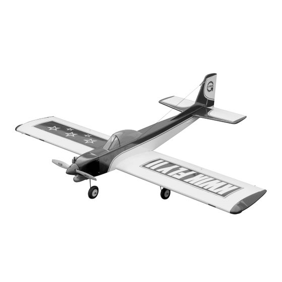
INSTRUCTIONS FOR FINAL ASSEMBLY
The Global Kwik Fly II ARF is distributed exclusively by
Specifications:
Global Hobby Distributors 18480 Bandilier Circle,
Fountain Valley, CA 92708
Wing Span: 66.5 Inches
Wing Area: 830 Square Inches
Length: 52.5 Inches
Weight RTF: 8 - 9 Pounds
Wing Loading: 22 - 25 Ounces Per Square Foot
All contents copyright © 2003, Global Hobby
Functions: Ailerons, Elevator, Rudder, Throttle & Optional Flap
Distributors Version V1.0 February 2003
Power: .61 - .91 2-Stroke or .80 - .91 4-stroke
Radio: 4 - 5 Channel w/5 - 6 Standard Ball Bearing Servos
Kit Product Number 125822
1
Need help or have any questions? Call us at 1-714-963-0329 or send us an e-mail at service@globalhobby.net
Advertisement
Table of Contents

Subscribe to Our Youtube Channel
Related Manuals for Global Hobby Kwik Fly II ARF

Summary of Contents for Global Hobby Kwik Fly II ARF
- Page 1 INSTRUCTIONS FOR FINAL ASSEMBLY The Global Kwik Fly II ARF is distributed exclusively by Specifications: Global Hobby Distributors 18480 Bandilier Circle, Fountain Valley, CA 92708 Wing Span: 66.5 Inches Wing Area: 830 Square Inches Length: 52.5 Inches Weight RTF: 8 - 9 Pounds Wing Loading: 22 - 25 Ounces Per Square Foot All contents copyright ©...
-
Page 2: Table Of Contents
Section 19: Final Assembly ............. 33 Section 20: Balancing the Kwik Fly II ARF ........36 Section 21: Lateral Balancing the Kwik Fly II ARF ......37 Section 22: Control Throws ............. 37 Section 23: Preflight Check & Safety ..........38 Section 24: Flying the Kwik Fly II ARF ........... -
Page 3: Introduction
INTRODUCTION Thank you for purchasing the Global Kwik Fly II ARF. Before completing the final assembly of your new airplane, please carefully read through this instruction manual in its entirety. Doing so will ensure your success the first time around! -
Page 4: Section 1: Our Recommendations
This section describes our recommendations to help you in deciding which types of accessories to purchase for your new Global Kwik Fly II ARF. These suggestions are not set in stone, but they should provide you with a good starting point. -
Page 5: Section 2: Tools And Supplies Required
SECTION 2: TOOLS AND SUPPLIES REQUIRED The tools and supplies listed below will be necessary to finish the final assembly of your Kwik Fly II ARF. We suggest having these items on-hand before beginning assembly. Electric Drill Kwik Bond Thin C/A # 887500... - Page 6 KIT CONTENTS CONTINUED..MAIN LANDING GEAR ASSEMBLY RUDDER CONTROL SYSTEM 23-3/4" Nylon Pushrod Prebent Main Gear Wires 5-7/8" Threaded Pushrod Wires Main Gear Wheels Nylon Control Horn w/Backplate Nylon Landing Gear Straps 2mm x 15mm Machine Screws 4mm Nylon Spacers Nylon Clevises 4mm Wheel Collars w/Set Screws C/A Style Hinges...
-
Page 7: Section 4: Replacement Parts
SECTION 4: REPLACEMENT PARTS Global stocks a complete line of replacement parts for your Global Kwik Fly II ARF. Listed below are the replacement parts that are available along with their respective part numbers for easy ordering convenience. We suggest ordering directly from your local dealer. -
Page 8: Section 6: Wing Assembly
SECTION 6: WING ASSEMBLY YOU'LL NEED THE FOLLOWING PARTS FROM THE KIT: (1) Hardwood Wing Joiner (1) Right Wing Panel w/Aileron (1) Left Wing Panel w/Aileron YOU'LL NEED THE FOLLOWING TOOLS AND SUPPLIES: Kwik Bond 30 Minute Epoxy Masking Tape Excel Modeling Knife Paper Towels Ruler... - Page 9 Slide both wing panels together with the wing joiner temporarily installed (without using glue). Look carefully at the center section joint: the wing panels should fit together tightly with few or no gaps in the joint. If the wing panels do not fit together properly, remove the wing joiner and use 220 grit sandpaper with a sanding block to lightly sand the edges and tips of the joiner, until you are satisfied with the fit.
-
Page 10: Section 7: Stabilizer Installation
SECTION 7: STABILIZER INSTALLATION YOU'LL NEED THE FOLLOWING PARTS FROM THE KIT: (1) Fuselage (2) 5mm x 50mm Machine Screws (1) Horizontal Stabilizer w/Elevator Halves (2) 5mm Flat Washers (1) Vertical Stabilizer w/Rudder YOU'LL NEED THE FOLLOWING TOOLS AND SUPPLIES: Kwik Bond 30 Minute Epoxy Builder's Triangle # 2 Phillips Head Screwdriver... - Page 11 Using a modeling knife, cut away and remove the covering material from over the horizontal and vertical stabilizer mounting slots in the back of the fuselage. Using a ruler and a pencil, measure and draw a vertical centerline across the top of the horizontal stabilizer. Carefully slide the stabilizer into the mounting slot, making sure that the trailing edge of the stabilizer, at the bottom, is even with the back edge of the fuselage.
- Page 12 When you are satisfied that the stabilizer is square to the wing, use a pencil to draw a couple of marks on each side of the front of the stabilizer where it and the fuselage sides meet, then use a couple of pieces of masking tape to hold the stabilizer firmly in place and aligned.
-
Page 13: Section 8: Control Surface Hinging
While holding the vertical stabilizer firmly in place, use a pencil to draw a line on each side of the stabilizer where it meets the top of the fuselage. Carefully draw an outline of the vertical stabilizer and the dorsal fin onto the top of the fuselage. Remove the stabilizer. -
Page 14: Section 9: Main Landing Gear Installation
Working with one aileron and wing panel for now, slide the aileron and its hinges into the precut hinge slots in the trailing edge of the wing panel, making sure that the leading edge of the aileron is pushed firmly up against the trailing edge of the wing panel and that the outer end of the aileron does not rub against the wing tip. - Page 15 Insert the 90º bend in one main gear wire into the predrilled hole in one landing gear mounting slot. Push the landing gear wire firmly down into the slot. The top of the wire should be nearly flush with the bottom of the wing.
-
Page 16: Section 10: Nose Gear Installation
SECTION 10: NOSE GEAR INSTALLATION YOU'LL NEED THE FOLLOWING PARTS FROM THE KIT: (2) 4mm Nylon Spacers (1) Prebent Nose Gear Wire (1) Nose Gear Wheel (2) 4mm Wheel Collars w/Set Screws (1) 18" Pushrod w/Z-Bend (1) Nylon Steering Arm w/Set Screw YOU'LL NEED THE FOLLOWING TOOLS AND SUPPLIES: # 2 Phillips Head Screwdriver Ernst Airplane Stand... -
Page 17: Section 11: Engine Installation
With the nose gear wire pushed down completely into the steering block, pivot it back and forth several times to check for free movement. The nose gear wire should pivot about 1/2" in each direction without binding. IMPORTANT To allow the nose gear wire to pivot smoothly, you may need to make a shallow bend in the pushrod wire where it exits the bottom of the fuselage. - Page 18 Using a ruler and a pencil, measure 2-7/8" up from the bottom of the firewall and draw a horizontal line. This line will be referred to as the "horizontal thrust line." Measure 1/4" to the right of the vertical centerline and draw a second vertical line parallel to it.
- Page 19 Divide the measurement found in the previous procedure in half. Measure this resulting distance and draw one horizontal line above and one below the horizontal thrust line. As an example, if using the Magnum XL .61ARNV, you would draw the two lines 1-1/16" above and 1-1/16" below the horizontal thrust line.
-
Page 20: Section 12: Fuel Tank Assembly & Installation
SECTION 12: FUEL TANK ASSEMBLY & INSTALLATION YOU'LL NEED THE FOLLOWING PARTS FROM THE KIT: (1) Fuel Pick-Up "Clunk" (1) 360cc Fuel Tank (1) Large Diameter Metal Plate (1) 3mm x 20mm Machine Screw (1) Small Diameter Metal Plate (1) Silicon Fuel Tubing (1) Rubber Stopper (2) Aluminum Tubing YOU'LL NEED THE FOLLOWING TOOLS AND SUPPLIES:... - Page 21 Step 2: Installing the Stopper Assembly Carefully push the stopper assembly into the molded hole in the front of the fuel tank. Gently rotate the stopper assembly until the aluminum vent tube rests just inside the bubble in the top of the tank. If you have trouble seeing the vent tube, hold the fuel tank assembly up to a bright light.
-
Page 22: Section 13: Servo Installation
SECTION 13: SERVO INSTALLATION YOU'LL NEED THE FOLLOWING PARTS FROM THE KIT: (1) Plywood Center-Flap Servo Tray YOU'LL NEED THE FOLLOWING TOOLS AND SUPPLIES: Kwik Bond 5 Minute Epoxy Pencil # 1 Phillips Head Screwdriver Paper Towels Excel Modeling Knife Rubbing Alcohol Electric Drill NHP Epoxy Mixing Sticks... - Page 23 Using a modeling knife, cut away and remove the covering material from over the precut aileron servo mounting holes in the wing. One hole is located in each half of the wing, 16-1/2" out from the centerline of the wing and 4" in front of the aileron hinge line.
-
Page 24: Section 14: Throttle Linkage Installation
SECTION 14: THROTTLE LINKAGE INSTALLATION YOU'LL NEED THE FOLLOWING PARTS FROM THE KIT: (1) 18" Pushrod Wire w/Z-Bend (1) Adjustable Servo Connector Assembly YOU'LL NEED THE FOLLOWING TOOLS AND SUPPLIES: Kwik Bond Thin C/A Excel Modeling Knife # 2 Phillips Head Screwdriver Electric Drill Wire Cutters 5/64"... -
Page 25: Section 15: Elevator Control System Installation
Position the throttle control stick and the throttle trim lever on your transmitter at their lowest positions. Slide the adjustable servo connector/servo horn assembly over the plain end of the throttle pushrod wire. After making sure that the carburetor is in the fully closed position, angle the servo horn back about 45º... - Page 26 Secure both 23-3/4" long pushrod tubes to the back of the nylon joiner plate using two 2mm x 10mm wood screws and two 2mm flat washers. Be sure to tighten the screws firmly. Apply a drop of thin C/A to each pushrod tube where it attaches to the joiner plate.
- Page 27 Slide the end of the pushrod tubes into the two nylon pushrod housings preinstalled in the fuselage. Install the servo horn onto the servo, making sure it's centered and points toward the middle of the fuselage. Install and tighten the servo horn retaining screw to secure the servo horn into place.
-
Page 28: Section 16: Rudder Control System Installation
SECTION 16: RUDDER CONTROL SYSTEM INSTALLATION YOU'LL NEED THE FOLLOWING PARTS FROM THE KIT: (1) Adjustable Servo Connector Assembly (1) Nylon Control Horn w/Backplate (1) 23-3/4" Nylon Pushrod (2) 2mm x 15mm Machine Screws (2) 5-7/8" Threaded Pushrod Wires (2) Nylon Clevises YOU'LL NEED THE FOLLOWING TOOLS AND SUPPLIES: Kwik Bond Thin C/A Electric Drill... - Page 29 Connect your radio system and plug the rudder servo lead into its proper slot in the receiver. Double-check that the rudder trim lever on your transmitter is centered. Slide the end of the pushrod into the preinstalled pushrod housing, then slide the adjustable servo connector over the end of the steering pushrod wire.
-
Page 30: Section 17: Aileron Control System Installation
SECTION 17: AILERON CONTROL SYSTEM INSTALLATION YOU'LL NEED THE FOLLOWING PARTS FROM THE KIT: (2) 3-1/8" Threaded Wires w/90º Bend (2) Nylon Clevises (2) Nylon 90º Snap Keepers (2) Nylon Control Horns w/Backplates (4) 2mm x 30mm Machine Screws YOU'LL NEED THE FOLLOWING TOOLS AND SUPPLIES: # 1 Phillips Head Screwdriver 5/64"... -
Page 31: Section 18: Center-Flap Control System Installation
Mount the control horn to the aileron, directly behind the pushrod wire, using two 2mm x 30mm machine screws. Make sure that the control horn is parallel to the hinge line and that the clevis attachment holes are over the hinge line. The centerline of the control horn should be approximately 7-1/4"... - Page 32 Step 2: Installing the Pushrod Assembly Thread the nylon clevis onto the pushrod wire and snap it into the outermost hole in the control horn. IMPORTANT If you don't plan on making the center-flap operable, please skip ahead to the photo & procedure at the top of the next page.
-
Page 33: Section 19: Final Assembly
If you don't want to utilize the center-flap assembly, you should make a 90º bend in the end of the pushrod wire and secure it to a servo arm using the nylon 90º snap keeper. Double-check that the center-flap is neutral, then secure the servo arm to the top of the plywood servo tray using a couple of small wood screws. - Page 34 Slide the cowling over the engine and onto the fuselage. With the cowling temporarily in place, secure the spinner backplate onto the engine's crankshaft. Line up the front of the cowling using the backplate as your guide. When aligned properly, the cowl ring should be centered with the spinner backplate and there should be about a 1/16"...
- Page 35 Test-fit the spinner cone over the propeller. Depending on the size of the propeller you are using, the spinner cone may not fit over it. If this is the case, use a modeling knife to very carefully enlarge the two cutouts in the spinner cone. It is important that the spinner cone not touch any part of the propeller when it is in place.
-
Page 36: Section 20: Balancing The Kwik Fly Ii Arf
Mount the switch into the precut switch mount in the fuselage side. Connect the battery lead to the switch and the switch and servo leads to the receiver. SECTION 20: BALANCING THE KWIK FLY II ARF YOU'LL NEED THE FOLLOWING TOOLS AND SUPPLIES:... -
Page 37: Section 21: Lateral Balancing The Kwik Fly Ii Arf
SECTION 21: LATERAL BALANCING THE KWIK FLY II ARF Lateral balancing will make the airplane easier to trim and will make it track straighter in the air. It is strongly recommended. With the airplane right-side up, tie one length of string to the propeller shaft and loop another piece of string around the fuselage right in front of the horizontal stabilizer. -
Page 38: Section 23: Preflight Check & Safety
SECTION 23: PREFLIGHT CHECK & SAFETY Completely charge the transmitter and receiver batteries before your first day of flying. Check every bolt and every glue joint in the airplane to ensure that everything is tight and well-bonded. This should include all of the control surface hinges as well. Double-check that you've installed and tightened all of the servo horn retaining screws. -
Page 39: Section 24: Flying The Kwik Fly Ii Arf
SECTION 24: FLYING THE KWIK FLY II ARF The Kwik Fly II ARF is designed for those pilots who are comfortable flying a trainer airplane and who might also have a few flights on a low-wing sport model. It is not a basic trainer. If you do not feel comfortable about test-flying the airplane, don't hesitate to ask someone more experienced for help. -
Page 40: Section 25: Kwik Fly Ii Arf Trimming Chart
SECTION 25: KWIK FLY II TRIMMING CHART After you have test-flown and done the initial trim changes to the airplane, use this trimming chart to begin trimming your airplane. Following and adhering to this chart will result in the ability to diagnose trim problems and correct those problems using the simple adjustments shown below. - Page 41 Need help or have any questions? Call us at 1-714-963-0329 or send us an e-mail at service@globalhobby.net...
- Page 42 Visit our website at http://www.globalhobby.com or for Customer Service at http://globalservices.globalhobby.com...
-
Page 43: Product Evaluation Sheet
Do not use staples and make sure our address faces out. Global Hobby Distributors will not disclose the information it collects to outside parties. Global Hobby Distributors does not sell, trade, or rent your personal information to others. - Page 44 Post Office will not deliver _____________________________ without proper postage (Return Address Here) Global Hobby Distributors Attn: Global Services 18480 Bandilier Circle Fountain Valley CA 92728-8610 Fold along dotted line Visit our website at http://www.globalhobby.com or for Customer Service at http://globalservices.globalhobby.com...
Need help?
Do you have a question about the Kwik Fly II ARF and is the answer not in the manual?
Questions and answers