
Related Manuals for Dynamic DX2-RJM

Summary of Contents for Dynamic DX2-RJM
-
Page 1: Installation Manual
Compact Remote Modules DX2-RJM, DX2-RJM-LF, and DX2-ACU Installation Manual GBK65701 DX2 Compact Remote Modules DX2-RJM, DX2-RJM-LF, and DX2-ACU Installation Manual Issue 1 December 2014... -
Page 3: Installation Manual Issue
Welcome to the Installation Manual for the DX2 compact remote modules: DX2-RJM, DX2-RJM-LF and DX2-ACU. This manual will help you understand, install, test and operate the DX2-RJM, DX2-RJM-LF and DX2- ACU remote modules. Please read and understand this and all other relevant DX2 system manuals before installing and operating. -
Page 4: Contact
GBK65701 DX2 Compact Remote Modules Installation Manual Issue 1 Dynamic Controls owns and will retain all trademark rights and Dynamic Controls or its licensors own and will retain all copyright, trade secret and other proprietary rights, in and to the documentation. -
Page 5: Table Of Contents
GBK65701 DX2 Compact Remote Modules Installation Manual Issue 1 2 Contents 2.1 Contents - overview 1 Welcome 2 Contents 3 Glossary 4 Introduction 5 Specifications 6 Installation 7 Operation 8 Testing 9 Diagnostics 10 Appendices 11 Index Contents - Page 3... -
Page 6: Contents - Overview
2.1 Contents - overview 2.2 Contents - detailed 2.3 Table of figures 3 Glossary 4 Introduction 4.1 Remote module overview 4.1.1 The DX2-RJM / DX2-RJM-LF 4.1.2 The DX2-ACU 4.2 Feature comparison 4.3 System overview 4.3.1 System configurations 4.3.2 Compatible master remote modules 5 Specifications 5.1 Mechanical specifications... -
Page 7: Diagnostics
7.2.6 Battery gauge indicator 7.2.7 Attendant indicator 7.2.8 Sleep mode 7.2.9 Lock mode 7.2.10 Configuration mode 8 Testing 8.1 Before testing 8.2 Testing the DX2-RJM / DX2-RJM-LF 8.2.1 Power button 8.2.2 User interface 8.2.3 Mode button 8.2.4 Joystick 8.2.5 Emergency stop 8.2.6 OONAPU 8.2.7 Wake up from sleep mode... -
Page 8: Index
2.3 Table of figures Figure 1: DX2-RJM and DX2-RJM-LF Figure 2: DX2-ACU Figure 3: System diagram Figure 4: Dimensions - DX2-RJM, DX2-RJM-LF and DX2-ACU Figure 5: Cable routing options Figure 6: Fixing centres Figure 7: Clamp diameter Figure 8: Clamp mount... -
Page 9: Glossary
3 Glossary Attendant Control Unit - a remote module used by a wheelchair attendant. See also RJM. Controller Area Network Dynamic Controls' modular mobility system DXBUS The DX system communication bus, comprising CAN communication lines plus power supply to DX modules. - Page 10 GBK65701 DX2 Compact Remote Modules Installation Manual Issue 1 Wizard A PC based programming, configuration and diagnostics tool used by the DX system. Page 8 - Glossary...
-
Page 11: Introduction
DX2-RJM-LF — DX2 RJM with low force joystick DX2-ACU — DX2 Attendant Control Unit (ACU) The DX2-RJM, DX2-RJM-LF and DX2-ACU are compact remote modules that share the same form, yet have different functions. The DX2-RJM and DX2-RJM-LF remote modules are designed for use by the wheelchair occupant, whereas the DX2-ACU has been designed for use as an attendant controller. -
Page 12: The Dx2-Acu
Able to be mounted in a variety of orientations to suit individual chair needs Fully sealed case design provides improved protection against water and dust ingress 4.2 Feature comparison Feature DX2-RJM DX2-RJM-LF DX2-ACU Suitable for wheelchair occupants Suitable for wheelchair attendants Lightweight, modern design Symmetrical design, ideal for left- and right-handed users. -
Page 13: System Overview
Not all master remote modules are compatible with the compact remote modules - for more details, see section 4.3.2 Compatible master remote modules. Figure 3: System diagram 4.3.1 System configurations The DX2-RJM, DX2-RJM-LF and DX2-ACU compact remote modules can be used in the following system configurations: Primary Secondary... -
Page 14: Compatible Master Remote Modules
DX/DX2 system, cannot be used in combination with another RJM-type module. 4.3.2 Compatible master remote modules The DX2-RJM, DX2-RJM-LF and DX2-ACU compact remote modules will only operate with UCM II based master remote modules. The following master remote modules are compatible with the DX2- RJM, DX2-RJM-LF and DX2-ACU compact remote modules. -
Page 15: Specifications
Nominal Units Operating temperature range °C Storage temperature range °C Operating humidity range Operating forces Nominal Units Joystick DX2-RJM / DX2-ACU DX2-RJM-LF Mode button < 2.5 Power button < 2.5 5.2 Electrical specifications Parameter Nominal Units Operating voltage (V batt... -
Page 16: Figure 4: Dimensions - Dx2-Rjm, Dx2-Rjm-Lf And Dx2-Acu
GBK65701 DX2 Compact Remote Modules Installation Manual Issue 1 Figure 4: Dimensions - DX2-RJM, DX2-RJM-LF and DX2-ACU Page 14 - Specifications... -
Page 17: Installation
The choice will depend on the type of compact remote (DX2-RJM/-LF or DX2-ACU) being installed and its user (wheelchair occupant or attendant): for a wheelchair occupant, the tray, clamp and base plate mount options may be suitable; for a wheelchair attendant, the tube or drop-in mount options may be more suitable. -
Page 18: Tray Mount
Installation Manual Issue 1 Note The mounts shown in the following sections are suggestions only; Dynamic Controls does not manufacture or supply the mounts. The OEM is responsible for the final design of the mount and its application. 6.1.2 Tray mount... -
Page 19: Tube Mount
GBK65701 DX2 Compact Remote Modules Installation Manual Issue 1 6.1.5 Tube mount The remote module can be fixed on to a tube using a suitable tube clamp. This solution is useful for tubes that run perpendicular to the remote module, as shown left. Figure 12: Tube mount (from above) The tube diameter will depend on the tube clamp used, and also the fixing hole centres on the... -
Page 20: Positioning
0.25 m. Note It is recommended that the low force compact remote module (DX2-RJM-LF) is not used as an attendant remote. If the remote is dropped, the mass of the remote, relative to the joystick deflection force, makes a runaway more likely than if the full deflection force joystick (DX2-ACU) is used. - Page 21 GBK65701 DX2 Compact Remote Modules Installation Manual Issue 1 Cables must be secured between their connectors and any point of flexing so that flexing forces are not transferred to the connectors. Warning Route and position cables and remote modules so that they are free from physical strain, abuse or damage, such as snagging, crushing, impacts from external objects, pinching or abrasion.
-
Page 22: Programming
Note Dynamic Controls recommends that you do not select ACU for the Joystick Source parameter for profiles 1 - 5. The ACU profile is automatically selected by the master remote module when the ACU takes control of a system. If another profile, other than the ACU profile, is selected and the profile has been configured with the ACU as the joystick source, then the Attendant indicator will not operate—the Attendant indicator only operates with the ACU... -
Page 23: Operation
7.2.10 Configuration mode 7.1 DX2-RJM, DX2-RJM-LF operation Note The following section details the operation for DX2-RJM and DX2-RJM-LF only. For a description of the DX2-ACU's operation, see section 7.2 DX2-ACU operation . The DX2-RJM and DX2-RJM-LF (low force joystick version) are drop-in replacements for the DX-RJM. They are... -
Page 24: The Joystick
Note To operate, the DX2-RJM and DX2-RJM-LF must be connected to a DX system via the DXBUS trailing lead. Warning Do not use the compact remote module if it is worn or damaged. Worn or damaged modules should be serviced immediately, especially if the DXBUS cable, joystick gaiter or keypad are ripped, torn or damaged. -
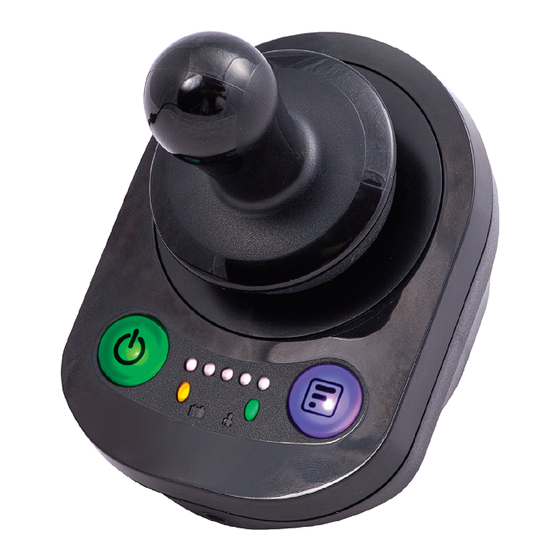
Page 25: Power Button And Status Indicator
GBK65701 DX2 Compact Remote Modules Installation Manual Issue 1 7.1.2 Power button and status indicator Note In the event that the wheelchair is in a runaway situation, press the remote module's power button to perform an EMERGENCY STOP. See section 7.1.3 Emergency stop. The power button is on the left-hand side of the remote module, and incorporates a status indicator that changes colour depending on the status of the system: Off - system OFF or... -
Page 26: Information Display
Short Increments drive profile. DX-REM41D/E Long Decrements drive profile. Note: The DX2-RJM cannot enter any accessory modes with these master remote modules. DX-ACU3B Short Increments drive profile. After the highest drive profile, it enters into actuator profile (if an actuator module is connected) and the mode button will not be responded to. -
Page 27: Battery Gauge Indicator
GBK65701 DX2 Compact Remote Modules Installation Manual Issue 1 Note Whenever a new drive profile is selected which has a different joystick source, the drive profile LEDs and the mode button LED will flash briefly. 7.1.6 Battery gauge indicator The battery gauge is situated below and left of the information display. -
Page 28: Attendant Indicator
ACU takes control of a system. If another profile, other than the ACU profile, is selected and the profile has been configured with the ACU as the joystick source, then this indicator will not operate. Dynamic Controls recommends that the Joystick Source parameter for profiles 1 - 5 is not programmed for ACU. See also 6.4.1 User profile options... -
Page 29: Lock Mode
ONLY be woken by pressing the power button. 7.1.9 Lock mode When a DX/DX2 system is locked, the DX2-RJM and DX2-RJM-LF user inputs and display are deactivated. A DX/DX2 system cannot be locked or unlocked with the DX2-RJM or DX2-RJM-LF, but the locked status can be displayed to the user when the user presses the power button. - Page 30 GBK65701 DX2 Compact Remote Modules Installation Manual Issue 1 7.1.10.2 Change display mode To change the display mode, press the mode button to scroll through the options. The battery gauge colour indicates the option: Display on Display off 7.1.10.3 Exit configuration mode To exit configuration mode, press the power button once.
-
Page 31: Dx2-Acu Operation
Note The following section details the operation of the DX2-ACU only. For a description of the operation of the DX2- RJM and DX2-RJM-LF, see section 7.1 DX2-RJM, DX2-RJM-LF operation . The DX2-ACU (attendant control unit) enables an attendant to take over control of a connected DX/DX2- based wheelchair. -
Page 32: The Joystick
GBK65701 DX2 Compact Remote Modules Installation Manual Issue 1 7.2.1 The joystick Warning The compact remote modules may only be used with the authorised joystick knobs. Use of any other joystick knob requires that the installer tests and confirms that the joystick returns to the neutral position whenever the joystick is deflected. -
Page 33: Emergency Stop
GBK65701 DX2 Compact Remote Modules Installation Manual Issue 1 If there is a fault with the system, the status indicator will indicate the fault with a series of red flashes (see section 9 Diagnostics). See also 7.2.10 Configuration mode 7.2.3 Emergency stop If the attendant needs to stop the wheelchair quickly, the power button can be pressed to perform an EMERGENCY STOP. -
Page 34: Speed Indicator
GBK65701 DX2 Compact Remote Modules Installation Manual Issue 1 If the occupant's remote module has control, a long press will switch the control to the DX2-ACU, and the Attendant indicator will light up to show that the DX2-ACU has control. If the DX2-ACU has control, a long press will switch the control to the occupant's remote module, and the Attendant indicator will switch off to show that the DX2-ACU does not have control. -
Page 35: Attendant Indicator
ACU takes control of a system. If another profile, other than the ACU profile, is selected and the profile has been configured with the ACU as the joystick source, then this indicator will not operate. Dynamic Controls recommends that the Joystick Source parameter for profiles 1 - 5 is not programmed for ACU. Operation - Page 33... -
Page 36: Sleep Mode
GBK65701 DX2 Compact Remote Modules Installation Manual Issue 1 See also 6.4.1 User profile options The system that has control is determined by the configuration mode setting and the mode button: 1. on powering up, the remote module that is initially in charge of the system is determined by the configuration mode setting;... -
Page 37: Configuration Mode
GBK65701 DX2 Compact Remote Modules Installation Manual Issue 1 7.2.10 Configuration mode The configuration mode sets which remote module has the initial control of the system at power up. The options are: 1. First in (default setting) - the remote module that powers the system up has control 2. - Page 38 GBK65701 DX2 Compact Remote Modules Installation Manual Issue 1 Page 36...
-
Page 39: Testing
Do not connect the battery positive (B+) terminal of the battery to the DX2 system until the wheelchair is lifted off the ground. To prevent the risk of injury, Dynamic Controls recommends the use of a lifting device when lifting the wheelchair off the ground. -
Page 40: User Interface
Test the emergency stop feature by pressing the power button while driving the wheelchair. For more information on the emergency stop feature, see 7.1.3 Emergency stop. Warning This procedure can be dangerous. Dynamic Controls recommends the use of a seatbelt to prevent the tester from slipping out of the seat. 8.2.6 OONAPU Test the OONAPU feature by powering up the wheelchair with the joystick out of the neutral (centre) position. -
Page 41: Testing The Dx2-Acu
Test the emergency stop feature by pressing the power button while driving the wheelchair. Warning This procedure can be dangerous. Dynamic Controls recommends the use of a seatbelt to prevent the tester from slipping out of the seat if the test is performed from the seat. -
Page 42: Wake Up From Sleep Mode
GBK65701 DX2 Compact Remote Modules Installation Manual Issue 1 Note Ensure that the DX2-ACU is set as the active module for this test. For more information on OONAPU, see 9.1 OONAPU. 8.3.7 Wake up from sleep mode Test the wake up feature when a system is asleep by one or both of the following: momentarily deflecting the joystick. -
Page 43: Diagnostics
GBK65701 DX2 Compact Remote Modules Installation Manual Issue 1 9 Diagnostics 9.1 OONAPU 9.2 Drive inhibit indication 9.3 Fault indication 9.4 Dealing with compact remote module faults 9.1 OONAPU OONAPU (“Out Of Neutral At Power Up”) is a safety feature that prevents accidental movement of the wheelchair, either when powering up, or when the wheelchair comes out of an inhibit state. -
Page 44: Fault Indication
GBK65701 DX2 Compact Remote Modules Installation Manual Issue 1 9.3 Fault indication When a fault occurs, a flash code is displayed on both the master remote module and the compact remote module. A flash code, which is displayed on the status indicator, is a number of flashes separated by a 1.6 second gap;... - Page 45 GBK65701 DX2 Compact Remote Modules Installation Manual Issue 1 Replace the DXBUS extension cable (if fitted). Replace the compact remote module. Note As it is commonplace for attendant control units to be disconnected while the wheelchair is powered up, if a DX2- ACU is disconnected while the wheelchair is powered up, and the Joystick Source parameter of any of the programmable profiles has not been set up for an ACU, then no flash code will be displayed.
- Page 46 GBK65701 DX2 Compact Remote Modules Installation Manual Issue 1 Page 44...
-
Page 47: Appendices
10.2 Intended use and regulatory statement 10.2.1 Intended use DX2-RJM and DX2-RJM-LF The DX2 Remote Joystick Modules, DX2-RJM and DX2-RJM-LF, are components of the DX/DX2 System, intended to allow powered wheelchair users to interact with the System. The DX2 Remote Joystick Modules allow control of drive functions, as well as operation of associated modules and compatible third-party equipment, as configured and connected within the DX/DX2 System. -
Page 48: Intended Use Dx2-Acu
The following instructions must be passed on to the operator before use of the product: Keep all Dynamic Controls electronic components free of dust, dirt and liquids. To clean the product, use a cloth dampened with warm soapy water. Do not use chemicals, solvents or abra- sive cleaners, as this may cause damage to the product. -
Page 49: Warranty
Warning There are no user-serviceable parts in any Dynamic Controls electronic component. Do not attempt to open any case or undertake any repairs, else warranty will be voided and the safety of the system may be compromised. -
Page 50: Service And Configuration Warnings
GBK65701 DX2 Compact Remote Modules Installation Manual Issue 1 Make sure that the battery charger that is used with the vehicle has a drive inhibit function that is correctly connected for use with the controller. If you are not sure, ask your dealer or vehicle manufacturer. -
Page 51: Electromagnetic Compatibility
Wiring Recommendations in the DX System Manual. 10.8 Environmental statement Dynamic Controls confirms that the product variants specified in this manual, as sub-assemblies of electronic and electrical equipment supplied for further integration by a medical device manufacturer, conform to applicable requirements of Directive 2011/65/EU, recast of Directive 2002/95/EC - Restriction of the use of certain Hazardous Substances in electrical and electronic equipment. -
Page 52: Other Symbols And Labels
Base/screw head Tamper evident seal 10.9.3 Serial number and date of manufacture The serial number on a Dynamic Controls product provides both the date of manufacture as well as a unique serial number for the particular module. Figure 37: Serial number example The format, as shown in Figure 37, is MYYnnnnnn, where: M is the month of manufacture, using the letters A to L (A = Jan, B = Feb, C = Mar, etc.),... -
Page 53: Index
DX2-ACU 9, 18 Quiescent current (power off) 13 DX2-REM420 12, 24 DX2-REM550 12, 24 DX2-REMA/B-ACS2 12 Safety and misuse warnings 47 DX2-RJM 9, 21 Serial number 50 DX2-RJM-LF 9, 21 Service life 46 DX2-RJM/-LF 18 Shipping weight 13 DXBUS 17, 21-22... - Page 54 GBK65701 DX2 Compact Remote Modules Installation Manual Issue 1 Tube mount 15, 17 UCM I 12 UCM II 12 Warranty 47 Who's in charge 31 Wiring 18 Page 52 - Index...
- Page 55 GBK65701 DX2 Compact Remote Modules Installation Manual Issue 1 Notes Index - Page 53...
- Page 56 Dynamic Controls was established in 1972 and is headquartered in New Zealand. Regional centres are located in Europe, United States, Asia, and Australasia. ISO 13485 certified – Dynamic Controls goes above and beyond industry standard expectations to ensure customers receive the best products possible. www.dynamiccontrols.com...
Need help?
Do you have a question about the DX2-RJM and is the answer not in the manual?
Questions and answers