Advertisement
Steambath Control
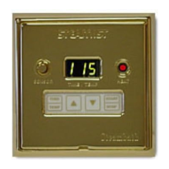
Control Features
1.
Temperature Sensor: Measures temperature inside
steamroom.
2.
Temperature/Timer Display: Counts down remaining
minutes and shows programmed minutes, set temperature,
and room temperature.
3.
Heat Light: Indicates the generator is producing steam when
illuminated. The heater in the generator and the heat light
will cycle ON/OFF as the temperature is maintained
automatically in the steamroom.
4.
Increase/Decrease, Temperature and Timer Set Keypads:
Press for a second to view the previously selected time/temp.
Press and hold to program the desired minutes or setpoint
temp.
5.
Start/Stop Keypad: Press to start programmed cycle, press
again to cancel cycle.
6.
Time/Temp Keypad: Press to select between time and
temperature.
Installation Instructions
IMPORTANT: This control MUST be installed inside the steam-
room for proper operation of the system.
The Digital ON/OFF Elapsed Timer/Temp Control is designed
to be connected and operated only with the Steamist SM
Steambath Generator and cannot be used with any other
equipment.
CAUTION: All electrical connections must be performed by a
licensed electrician in accordance with Local and National
Electrical Codes. Power must be OFF until all wiring is complete.
1. Remove the cover from the Steambath Generator. Insert
multi-conductor cable with strain relief (provided) through
cabinet knockout and secure the cable to the top of the
steambath generator leaving 8" of cable inside the generator.
Remove the protective covering labeled "Remove Before
Installation" from the Telco Jack found on the Circuit Board.
Remove protective cap from plug and insert Steamist cable
into Telco Jack; check that the orientation of the plug properly
aligns with the jack. A snap will indicate the plug is installed
correctly (see Figure 1). Close and secure Generator cover.
WARNING: Elderly persons, pregnant women, or those suffering from heart disease, high blood pressure, diabetes, or
who are otherwise not in good health, do not use this device unless directed to do so by a physician. Also, do not use
!
steambath while under the influence of alcohol. For additional Important Safety Information, please see a separate
instruction sheet Pub. No. 199.
IMPORTANT: The DSC-425 Controls will only function with one of the following Steamist Generator models: SM-46, SM-79, SM-4,
SM-5, SM-7, SM-8, SM-11, SM-12, SM-15, System-18, System-24, System-30, with or without the InstaMist feature.
02/09
®
DSC-425 Digital Timer and Digital Temperature Control
1
6
4
NOTE: The DSC-425 Control should be stored in the
protective box until the wall is completed and is ready
to be installed.
2. Select a mounting location inside the steamroom for the
DSC-425 Control, 4 feet above the floor, convenient to
the bather. Do NOT locate in direct line of shower head
spray or above steamhead (see Figure 6). Mount 2
metal, gangable switch boxes, twinned together (not
provided) in this location. Do NOT use a 4x4 electrical
box.
- 1 -
Installation and Operating Instructions
Model: DSC-425
SENSOR
HEAT
TIME / TEMP
TIME
START
TEMP
STOP
Pub. No. 120-F
C
US
®
2
3
5
Advertisement
Table of Contents

Summary of Contents for Steamist DSC-425
- Page 1 For additional Important Safety Information, please see a separate instruction sheet Pub. No. 199. IMPORTANT: The DSC-425 Controls will only function with one of the following Steamist Generator models: SM-46, SM-79, SM-4, SM-5, SM-7, SM-8, SM-11, SM-12, SM-15, System-18, System-24, System-30, with or without the InstaMist feature.
- Page 2 3. Carefully route the other end of the multi-conductor control IMPORTANT: DSC-425 Control MUST be mounted inside cable from the Steambath Generator to the DSC-425 inside the steamroom. Silicone sealant (supplied) MUST be used the steamroom. Route multi-conductor cable through a ¾"...
- Page 3 Installation and Operating Instructions Figure 3 Model: DSC-425 To Generator IMPORTANT: Run the Control Cable through a ¾" Conduit. Reverse Base Plate Strain Relief Coupler #6-32 x 2" Long Stainless Steel Screw, 4 Places Face Plate Double-Sided Adhesive Tape 2 Places the steamhead O-ring is fully seated into the Back Plate.
- Page 4 This control is programmed with a diagnostic connections get wet. feature to help isolate any potential problems. Error messages Figure 6 Typical location of the DSC-425 Control. Locate away from the direct line of shower spray and do Steamhead Installation NOT locate above steamhead.
Need help?
Do you have a question about the DSC-425 and is the answer not in the manual?
Questions and answers