Table of Contents
Advertisement
Quick Links
Advertisement
Table of Contents

Summary of Contents for Ikan Blitz 400
- Page 2 Preface Thank you for purchasing the Ikan Blitz 400 HD Wireless Video System. This system features uncompressed high definition video with zero delay. Before using the product, please read this user’s manual. If you have any further questions or comments please visit www.ikancorp.com...
- Page 3 Cautions ■Cautions 1. Do not expose this product to extreme hot, cold, dusty or humid conditions. 2. Avoid dropping the product or it may damage the hardware. 3. Do not spill or get any liquid on the unit since it is not waterproof. 4.
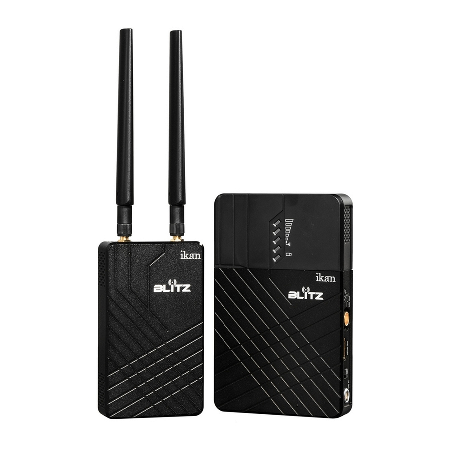
- Page 4 3G/HD SDI input and an HDMI input, and the receiver also provide a 3G/HD SDI output and an HDMI output. The Blitz 400 has 2 external antennas on the transmitter and 5 internal antennas on the receiver’s side. Both the...
- Page 5 About ■Main features: Supports HDMI 1.3 HDMI and SD/HD/3G SDI input and output Up to 1080p 60 Hz uncompressed with zero delay AES-128 encryption with air interface HD video data stream Supports point-to-point, and point-to-multipoint network topology 5GHz ISM frequency band, maximum of 10 frequency channels selected by user knob, coexist with WIFI.
-
Page 6: Specifications
About ■Specifications: Transmitter Receiver SDI Input( BNC Female ) HDMI ; SDI Output( BNC Female ) HDMI ; Input (Type A female) ; 2 Antenna port(RP- Output (Type A female); DC input Interface SMA male) ; DC input Supply voltage range 7-36V DC 7-36V DC Power consumption... -
Page 7: Specification
About ■Specification: Transmitter 1) ¼”-20 Screw Hole 2) RP-SMA male antenna connector 3) Video input indicator, 1 yellow LED 4) Power on Indicator, 1 green LED 5) Frequency selection knob 6) SD/HD/3G SDI input 7) HDMI Input 8) DC power switch 9) DC input, LEMO 4-pin B series connector... - Page 8 About ■Parameters: 67 8 Receiver 1) ¼”-20 Screw Adapter 2) LED status indicator (4 blue LED for RSSI &1 LED yellow for POWER/VIDEO) 3) Frequency selection knob 4) SD/HD/3G SDI output 5) HDMI output 6) DC power switch 7) DC input, LEMO 4-pin B series connector...
-
Page 9: Packing List
About ■Packing list: 1 x Transmitter 1 x Receiver 2 x Sony L Series Battery Plates (Installed) 2 x 5 GHz omni-directional antennas (SMA female) 2 x P-Tap to Lemo Cables 1 x 6 in. Articulating Arm 1 x Clamp 1 x Shoemount adapter for transmitter... -
Page 10: Transmitter Side
Installation ■Installation details and cautions Transmitter side a) Install 2 Omni-directional antennas to the transmitter's RP-SMA female antenna connectors. b) There is one ¼”-20 threaded receiver on the bottom of the transmitter so the user can utilize the included shoemount adapter to attach the transmitter onto a camera. -
Page 11: Receiver Side
Installation Receiver side a) There is one ¼”-20 mount on the bottom side of the receiver. The user can utilize the included 6' in. articulating arm and clamp to install the receiver on a tripod. b) Install battery on to the battery plate. Unit comes installed with a Sony L Series type battery plate. - Page 12 Installation Typical connection instructions Connect the camera’s SDI or HDMI output to the corresponding input port and affix the transmitter to the hot shoe port of the camera. Connect the HDMI or SDI output port of the receiver to the SDI or HDMI input port of the HD monitor.
-
Page 13: Getting Started
Operation instruction Getting started After finishing all the steps above, the system is ready to use. See below for the following steps. a) Ensure the source output of the camera is OK and the monitor is powered on. Then switch to the connected video input. b) Ensure input and output SDI or HDMI cables are connected. - Page 14 Installation e) Ensure the frequency knobs of transmitter and receiver are set to the same number. This will ensure that the transmitter and receiver will be set to the same RF frequency. f ) If the camera is on and outputting video the TX side 'video' light will turn on. g) Before the RX has finished its wireless link with the TX, the 4 'RSSI' indicators and 'Video' indicators will be off.
- Page 15 Visible Video Noise ■Frequency selection and configuration The Blitz 400 can work in the 5.1-5.9GHz frequency band. The side panels of both the transmitter and receiver have a frequency selection knob, which provides a maximum of 10 workable frequency channels. The system supports a maximum of 4 sets working simultaneously.
- Page 16 Maintenance ■Storage conditions Product storage temperature should be between -20°C~60°C. For long term storage requirement, please use original hard case, and avoid storing in high humidity, acidic or dusty conditions. ■Maintenance Warning To ensure your safety and the reliable performance of this system provide stable power within 7 –...
-
Page 17: Frequently Asked Questions
Trouble shooting ■Frequently Asked Questions a) No output on display - Check that the TX and RX have stable power. - Double check that the batteries are charged. - Check that the TX and RX antennas are installed correctly. - Check the 'Video' indicator, if TX 'Video' indicator is not lit, then check if the SDI or HDMI cable is plugged in and a video source is present. - Page 19 Conditions of Warranty Service Free service for one year from the day of purchase if the problem is caused by manufacturing errors. The components and maintenance service fee will be charged if the warranty period is expired. Free Service will not be provided in the Following Situations: (*Even if the product is still within the warranty period).
Need help?
Do you have a question about the Blitz 400 and is the answer not in the manual?
Questions and answers