Table of Contents
Advertisement
Quick Links
Download this manual
See also:
Service Manual
Advertisement
Table of Contents

Subscribe to Our Youtube Channel
Related Manuals for innovair ICS0629C21


Summary of Contents for innovair ICS0629C21
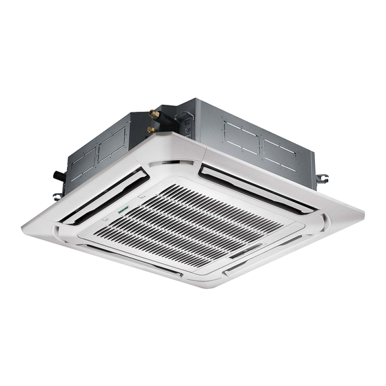
- Page 1 INSTALLATION MANUAL Four-way Inverter Cassette Type ICS0629C21 ICS0736C21 ICS0848C21 Thank you very much for purchasing our air conditioner, Before using your air conditioner , please read this manual carefully and keep it for future reference.
-
Page 2: Table Of Contents
Install according to this installation instructions strictly. If installation is defective, it will cause water leakage, electrical shock and fire. CONTENTS CONTENTS PAGE PAGE When installing the unit in a small room, take measures against to keep refrigerant concentration from exceeding PRECAUTIONS.............. -
Page 3: Installation Information
If the refrigerant leaks during installation, ventilate the The appliance shall be installed in accordance with area immediately. national wiring regulations. Toxic gas may be produced if the refrigerant comes into the place contacting with fire. Do not operate your air conditioner in a wet room such as a bathroom or laundry room. -
Page 4: Attached Fittings
3. ATTACHED FITTINGS Please check whether the following fittings are of full scope. If there are some spare fittings , please restore them carefully. NAME SHAPE QUANTITY 1. Installation paper board Installation Fittings (on some models) 2. Soundproof / insulation sheath Tubing &... -
Page 5: Inspecting And Handling The Unit
4. INSPECTING AND HANDLING THE UNIT 5.3.1 Install the main body(cassette type air conditioner) At delivery, the package should be checked and any damage should be reported immediately to the service agent. The existing ceiling (to be horizontal) When handling the unit, take into account the following: Cut a quadrangular hole of 880x880mm in the ceiling according to the shape of the installation paper board. - Page 6 Table 5-1 Remark MODEL Tubing side Drain side >260 R410A &R22 Cooling/Cooling & Heating >260 R410A &R22 Cooling/Cooling & Heating >330 R410A &R22 Cooling/Cooling & Heating >330 30~60 R410A &R22 Cooling/Cooling & Heating Drain piper piping 780(Hook-location) (Unit: mm) 840(Body) 950(Panel) Inner insulation Side plate...
- Page 7 Leakage Ceiling Pollution Water condensation Grid switch Fig.5-14 Fig.5-9 Loosen upper nut Gap not allowed Adjust lower nut Fig.5-10 Fig.5-15 Installation cover’s rope Slide the four sliders Tap Screw Fig.5-11 in the corresponding channel when installing the cover Fig.5-16 Tubing joint Hook panel Outlet joint 1-1.5m...
- Page 8 5.3.2 Install the main body(small cassette type air conditioner) Necessary room Colourless Horizontal trans parent pipe indicator Fig.5-23 Outlet Inlet Outlet Ground Fig.5-19 >1000 Fig.5-24 Central hole Fresh air intake (ф65) Body >1000 Fixing hole Hook hole installation paper board Fig.5-20 Screw M5x16 (Accessory)
- Page 9 Install the panel Align the swing motor on the panel to the tubing joints of the body properly. ( Refer to Fig.5-12) Fix hooks of the panel at swing motor and its opposite sides to the hooks of corresponding water receiver. ( Refer to Fig.5-12.1) Then hang the other two panel hooks onto corresponding hangers of the body.
- Page 10 Drain side Steel rope Steel rope Ceiling Leakage Swing motor installation cover Cover Swing motor installation cover Cover Swing motor side Please operate according Bolt, washer to the direction of the arrow, or it can not be disassembled when it is necessary. Fig.5-31 Fig.5-29 Body...
- Page 11 NOTE Fresh air model 18 to 24 Series A=350mm; Series B=85mm Distribution duct Distribution duct model 36 to 60 Series A=350mm; Series B=155mm One-way Fresh air intake ( 75) MODLE (12-18) Two- way Ø65mm Ø75mm Fig.5-35 Fig.5-34 NOTE In case of one duct connection model 12 to 18 Series A=150mm The air volume in duct is around 300-360m3/h for model 18...
-
Page 12: Outdoor Unit Installation
6. OUTDOOR UNIT INSTALLATION 6.1 Installation Place The outdoor unit should be installed in the location that meets the following requiements: There is enough room for installation and maintenance. The air outlet and the air inlet are not impeded, and can not be reached by strong wind. - Page 13 6.2 Figure of body size Table 6-1 MODEL 1. Split type outdoor unit Fig.6-2 Fig.6-2 Fig.6-2 Fig.6-2 Fig.6-2 Fig.6-2 Fig.6-2 Fig.6-2 Fig.6-2 Fig.6-2 1369 Fig.6-3 Fig.6-2 Fig.6-2 1369 Fig.6-3 Fig.6-2 1369 Fig.6-3 1170 Fig.6-3 1170 Fig.6-3 1369 Fig.6-3 2. Vertical discharge type outdoor unit Fig.6-3 Fig.6-5 Fig.6-4...
- Page 14 2. Vertical discharge type outdoor unit Table 6-2 (Wall or obstacle) DIMENSIONS MODEL REMARK Refore to Fig.6-5 Fig.6-6 3. Centrifugal fan outdoor unit Fig.6-9 (Wall or obstacle) >300mm Fig.6-7 Air inlet Table 6-3 >300mm Air inlet MODEL 1174 1120 1174 1120 680 30-36 1381 1328...
- Page 15 b)In case that installing on the floor To change air outlet is necessary to interchange panels too. Fan outlet panel is attached to fan structure, which must be mounted as follow Fig.6-12 Fig.6-14 NOTE All the figures in this manual are for explanation 6.5 Moving and installation purpose only.
-
Page 16: Install The Connecting Pipe
7. INSTALL THE CONNECTING PIPE Concrete Foundation Foundation could be on flat and is recommended be 100-300mm higher than ground level. Check whether the height drop between the indoor unit and Install a drainage around foundation for smooth drain outdoor unit, the length of refrigerant pipe, and the number of When installing the outdoor unit fix the unit by anchor bolts of the bends meet the following requirements: M10. - Page 17 Remove the protection cover of stop valve Bind the connecting pipe and the cables together tightly with binding tapes. Pass the bound connecting pipe through the wall conduct from outside. Be careful of the pipe allocation to do on damage to the tubing. Connect the pipes.
- Page 18 Table 7-3 Additional Refrigerant Charge Tightening torque N M (Turn clockwise to close) Stop Shaft (valve body) CAUTION Maintenance nut Valve size (Valve lid) Ø6.35 5~7 13.5~16.5 Hexagonal Ø9.52 wrench 4 mm Refrigerant cannot be charged until field wiring has been Ø12.7 7~9 18~22...
-
Page 19: Connect The Drain Pipe
Table7-6 Drainage test Drainage test MODEL Unit Check whether the drainpipe is unhindered. 18~24 1200 New built house should have this test done before paving the ceiling. 30~36 1381 Remove the test cover, and stow water of about 2000ml to the 1385 water receiver through the stow tube. -
Page 20: Connective Diagram
9. CONNECTIVE DIAGRAM Cooling only Liquid side Indoor Outdoor Gas side Liquid side Liquid side Outdoor Indoor Orifice Liquid side Fig. 9-1 Indoor Outdoor NOTE For ensuring throttled efficiency , Please mount the Orifice assembly as horizontally as possible; and anti-shock rubber Fig. -
Page 21: Wiring
10. WIRING 1. Split type outdoor unit The appliance shall be installed in accordance with national wiring regulations. Cover The air conditioner should use separate power supply with rated voltage. The external power supply to the air conditioner should have ground wiring, which is linked to the ground wiring of the indoor and outdoor unit. -
Page 22: Test Operation
11. TEST OPERATION The test operation must be carried out after the entire installation has been completed. Please confirm the following points before the test operation: The indoor unit and outdoor unit are installed properly. Tubing and wiring are correctly completed. The refrigerant pipe system is leakage-checked. - Page 23 The Specification of Power(indoor power supply) Table 10-1 30~36 42~48 MODEL 1 P h a s e 1 P h a s e 1 P h a s e 1 P h a s e 1 P h a s e PHASE POWER 208-240 V...
- Page 24 The Specification of Power(independence power supply) Table 10-6 30~36 42~48 MODEL 1 P h a s e 1 P h a s e 1 P h a s e 1 P h a s e 1 P h a s e PHASE POWER (indoor)
- Page 25 CAUTION The power supply is included in the power supply above mentioned can be applied to the table. Before obtaining access to terminals, all supply circuits must be disconnected. Wiring figure Fig.10-4 Power supply Switch/Fuse (Available locally) Power wiring (indoor) Power linking wiring (Outdoor) Indoor Outdoor...
- Page 26 Fig.10-6 Power supply Power supply Switch/Fuse (Available locally) Power wiring (indoor) Power linking wiring (Outdoor) Indoor Unit Out door Unit Ground wiring Weak elec-signal link wiring Ground wiring Ground the air conditioner properly in case to affect its anti-interference function CAUTION A disconnection device having an air gap contact separation in all active conductors should be incorporated in the fixed wiring according to the National Wiring Regulation.
- Page 27 QSQ4I-017AEN The design and specifications are subject to change without prior notice for product improvement.Consult with the sales agency or manufacturer for details. 202000192506 20140414...
- Page 30 installation manual...
- Page 31 installation manual...
- Page 32 installation manual...
- Page 33 installation manual...
- Page 34 installation manual...
- Page 35 installation manual...
- Page 36 installation manual...
- Page 37 installation manual...
- Page 38 installation manual...
- Page 39 installation manual...
- Page 40 installation manual...
- Page 41 installation manual...
Need help?
Do you have a question about the ICS0629C21 and is the answer not in the manual?
Questions and answers