Table of Contents
Advertisement
Quick Links
Installation
Start-Up
Maintenance
Parts
Warranty
MODCON500 / 700 / 850
VWH Models*
*"VWH" Denotes Hot Water Supply Boiler
"LP" Denotes Propane Gas Operation
"HL" Denotes Installed High and Low Gas Pressure
Switches
"WL" Denotes Installed High Temperature Water Limit
This manual must only be used by a qualified installer / service technician. Read all instructions in this manual before
installing. Perform steps in the given order. Failure to do so could result in substantial property damage, severe
personal injury, or death.
Improper installation, adjustment, alteration, service, or maintenance could void product warranty and cause
property damage, severe personal injury, or death.
HTP reserves the right to make product changes or updates without notice and will not be held liable for typographical
errors in literature.
The surfaces of these products contacted by potable (consumable) water contain less than 0.25% lead by weight as
required by the Safe Drinking Water Act, Section 1417.
NOTE TO CONSUMER: PLEASE KEEP ALL INSTRUCTIONS FOR FUTURE REFERENCE.
272 Duchaine Blvd.
Volume Water Heaters
This Manual For Use With Boilers Manufactured After
New Bedford, MA 02745
Mod Con
August 13, 2013
Heat Exchanger Bears the ASME "H" Stamp
www.htproducts.com
LP-446-r4 Rev. 10.12.16
Advertisement
Table of Contents

Summary of Contents for Mod Con MODCON500
- Page 1 Volume Water Heaters Installation Start-Up Maintenance Parts Warranty MODCON500 / 700 / 850 VWH Models* *“VWH” Denotes Hot Water Supply Boiler “LP” Denotes Propane Gas Operation “HL” Denotes Installed High and Low Gas Pressure Switches “WL” Denotes Installed High Temperature Water Limit...
- Page 2 IF THE INFORMATION IN THIS MANUAL IS NOT FOLLOWED EXACTLY, A FIRE OR EXPLOSION MAY RESULT, CAUSING PROPERTY DAMAGE, PERSONAL INJURY, OR LOSS OF LIFE. DO NOT STORE GASOLINE OR OTHER FLAMMABLE VAPORS AND LIQUIDS IN THE VICINITY OF THIS OR ANY OTHER APPLIANCE. WHAT TO DO IF YOU SMELL GAS •...
- Page 3 having statutory authority. In some circumstances, the property owner or his/her agent assumes the role, and at government The following defined terms are used throughout this manual installations, the commanding officer or departmental official to bring attention to the presence of hazards of various risk may be the AHJ.
-
Page 4: Table Of Contents
J. Applications Part 5 - Venting and Condensate Removal The CSD-1 ASME Code, Section CW-400 requires that hot A. General water heating and supply boilers have a) a UL 353 temperature B. Approved Materials for Exhaust Vent and Intake Pipe control device, b) at least one (1) temperature-actuated control C. -
Page 5: Part 1 - General Safety Information
D. User Interface Display Part 12 - Maintenance This boiler has been designed to heat potable water ONLY. A. Procedures Using this boiler to heat non-potable fluid WILL VOID product B. Combustion Chamber Coil Cleaning Instructions warranty, and could result in property damage, personal injury, C. -
Page 6: Boiler Water
D. Boiler Water Do not use petroleum-based cleaning or sealing compounds in a water heating system. Gaskets and seals in the system may be damaged. This can result in substantial property damage. Do not use “homemade cures” or “patent medicines”. Damage to the boiler, substantial property damage, and/or serious personal injury may result. -
Page 7: Part 2 - Before You Start
Part 2 - Before You Start CAUTION VWH units must be connected to a storage tank. You must not have a direct connection of the potable water system into the heat exchanger. This could cause flow issues, short cycling, and an increase of mineral build-up in the unit. This system is designed to have incoming potable water flow through the storage tank first, then through the heat exchanger. -
Page 8: What's In The Box
system spark electrode. The spark from the electrode ignites A. What’s in the Box mixed gas off of the burner. Remove all sides of the shipping crate of the boiler. Supply Water Temperature Sensor Components included with the boiler: This sensor monitors the boiler outlet water temperature •... -
Page 9: Part 3 - Prepare The Boiler
1. Installation Area (Mechanical Room) Operating Conditions Part 3 - Prepare the Boiler • Ensure ambient temperatures are higher than 32 F / 0 Remove all sides of the shipping crate to allow the boiler to and lower than 104 F / 40 be moved into its installation location. -
Page 10: Flooring
The service life of the boiler’s exposed metallic surfaces, such Assure that the floor and structure of the installation location as the casing, as well as internal surfaces, such as the heat are sufficient to support the full installed weight of the exchanger, are directly influenced by proximity to damp and boiler, including water content of the heat exchanger and salty marine environments. -
Page 11: Residential Garage And Closet Installations
F. Exhaust Vent and Intake Pipe The boiler is rated ANSI Z21.13 Category IV (pressurized vent, All boilers eventually leak. It is recommended to install a likely to form condensate in the vent) and requires a special vent catch pan beneath the boiler. This catch pan should be sized system designed for pressurized venting. -
Page 12: Direct Vent Of Exhaust And Intake
1. Direct Vent of Exhaust and Intake If installing a direct vent option, combustion air must be drawn from the outdoors directly into the boiler intake and exhaust Failure to provide an adequate supply of fresh combustion must terminate outdoors. There are three basic direct vent air can cause poisonous flue gases to enter the living space, options detailed in this manual: 1. -
Page 13: Water Chemistry Requirements
When removing an existing boiler, follow the steps below. I. Water Chemistry Requirements* 1. Seal any unused openings in the common venting system. 2. Visually inspect the venting system for proper size and horizontal pitch to determine if there is blockage, leakage, Chemical imbalance of the water supply may affect efficiency and corrosion, or other deficiencies that could cause an unsafe cause severe damage to the boiler and associated equipment. -
Page 14: Part 4 - Piping
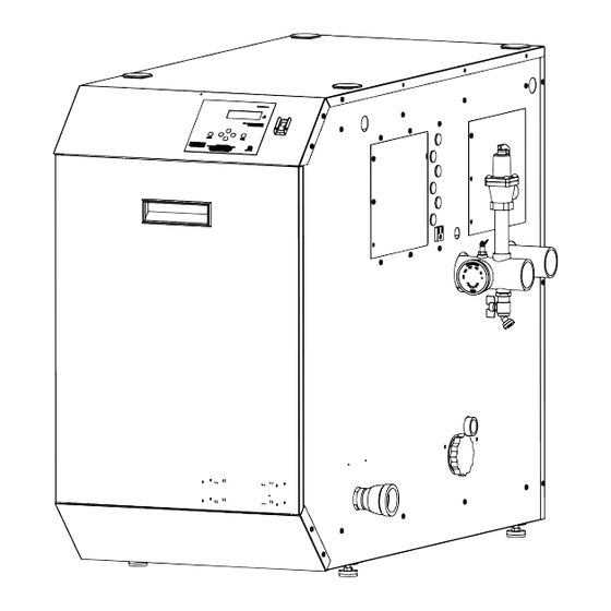
Figure 5 - Boiler Dimensions - NOTE: All Dimensions Are Approximate - VWH in Model Number Denotes Volume Water Heater Model Part 4 - Piping Failure to follow the instructions in this section WILL VOID the Dielectric unions or galvanized steel fittings must not be used warranty and may result in property damage, severe personal in a system with this boiler. -
Page 15: General Plumbing Information
Plumbing of this product should only be done by a qualified, entire length. licensed plumber in accordance with all local plumbing codes. • Discharge line must pitch downward from the valve The boiler is designed to be connected to a storage tank to supply and terminate at least 6”... -
Page 16: Circulators
for potable water use. The expansion tank should be located on protect against the cold inlet piping close to the boiler. injury, install a mixing Expansion Tank and Make-Up Water valve in the water 1. Ensure that the expansion tank is sized to correctly handle system. - Page 17 500 Model 700/850 Models Table 7 - Heat Exchanger Pressure Drop The chart below represents various system design temperature rise through the boiler along with respective flows and friction loss. This is provided to aid in circulator selection. System Temperature Rise Chart 20°Δt 25°Δt 30°Δt...
-
Page 18: Water Chemistry
in the heat exchanger. Heat exchanger failure due to total H. Water Chemistry dissolved solids in excess of 2,000 ppm is a non-warrantable condition. Failure of a boiler due to lime scale build up on the heating surface IS NOT covered by the warranty. Chemical imbalance of the water supply may affect efficiency and cause severe damage to the boiler and associated equipment. -
Page 19: Applications
I. Applications System / Pipe Sensor Indirect / Used if sensor cannot be placed at tank Tank (Important to note that pumps must be wired Sensor to run continuously to operate in this configuration) Preferred Location Storage Tank Figure 6 - Piping Legend Figure 7 - VWH Boiler with Storage Tank FIGURE NOTES: 1. - Page 20 FIGURE NOTES: 1. This drawing is meant to show system piping concept only. Installer is responsible for all equipment & detailing required by local codes. 2. Boiler circulator must be rated for open loop application. Do not use cast-iron circulators. Boiler circulator(s) operate...
- Page 21 System / Pipe Sensor Used if sensor cannot be placed on tank (Important to note that pumps must be wired to run continuously to operate in this configuration) this configuration) required Storage Tank system / pipe sensor Figure 11 - Two Stacked VWH Boilers with Two Storage Tanks Storage Tank Figure 12 - Three VWH Boilers with Two Storage Tanks FIGURE NOTES:...
-
Page 22: Part 5 - Venting And Condensate Removal
Part 5 - Venting and Condensate Removal The boiler must be vented as detailed in this section. Ensure exhaust vent and intake piping complies with these instructions regarding vent system. Inspect finished exhaust vent and intake piping thoroughly to ensure all joints are well secured, airtight, and comply with all applicable code requirements, as well as the instructions provided in this manual. -
Page 23: Approved Materials For Exhaust Vent And Intake Pipe
B. Approved Materials for Exhaust Vent and Intake Pipe Standards for Installation In: Item Material United States Canada PVC Schedule 40/80 ANSI / ASTM D1785 PVC, CPVC, and PP Venting Must PVC-DWV* ANSI / ASTM D2665 be ULC-S636 Certified. IPEX is Exhaust Vent or Intake an approved manufacturer in CPVC Schedule 40/80... -
Page 24: Exhaust Vent And Intake Pipe Location
D. Exhaust Vent and Intake Pipe Location Area Where Terminal Is Not Permitted Exhaust Vent Terminal Intake Pipe Terminal Figure 13 - Exit Terminals for Direct Vent Systems - ANSI Z223.1 / NFPA 54 for US and CAN/CSA B149.1 for Canada DETERMINE EXHAUST VENT AND INTAKE PIPE LOCATION –... -
Page 25: Exhaust Vent And Intake Pipe Sizing
E. Exhaust Vent and Intake Pipe Sizing Standard Increased Vent Size 1. The exhaust vent and intake pipe size is 4” for the 500 model Vent Connection and Reducing and Maximum Total and 6” for the 700/850 models. Maximum Total Coupling Equivalent Length 2. -
Page 26: Applications
over existing chimney openings. 13. All piping must be fully supported. Use pipe hangers at a Two Pipe Roof Venting with Intake (Elbow) and minimum of 4 foot intervals to prevent sagging of the pipe Exhaust (Coupling) where condensate may form. 14. -
Page 27: Sidewall Venting
Sidewall Venting with Kit Figure 16 - Venting with Optional Kits (NOT INCLUDED WITH THE BOILER) NOTE: These drawings are meant to demonstrate system venting only. The installer is responsible for all equipment and detailing required by local codes. SIDE VIEW FRONT VIEW All vent pipes must be glued, properly supported, and the exhaust pitched a minimum of 1/4”... - Page 28 Figure 18 - Unbalanced Venting - Roof Exhaust and Sidewall Intake NOTE: These drawings are meant to demonstrate system venting only. The installer is responsible for all equipment and detailing required by local codes. All vent pipes must be glued, properly supported, and the exhaust pitched a minimum of 1/4”...
-
Page 29: Room And Indoor Combustion Ventilation Requirements
2. Room and Indoor Combustion Ventilation Requirements When using an indoor combustion air installation, the mechanical room MUST be provided with properly sized openings, and/or be of sufficient volume to assure adequate combustion air and proper ventilation for all gas fired appliances in the mechanical room to assure adequate combustion air and proper ventilation. -
Page 30: Condensate Removal System
I. Condensate Removal System NOTE: Check with your local gas company to determine if Under no circumstances should the mechanical room ever combustion condensate disposal is permitted in your area. In be under negative pressure. Particular care should be taken the state of Massachusetts, condensate must be neutralized where exhaust fans, attic fans, clothes dryers, compressors, air before entering a drain. -
Page 31: Part 6 - Wiring
Pumps To avoid electrical shock, turn off all power to the boiler prior The Mod Con VWH application requires a circulator pump to opening an electrical box within the unit. Ensure the power for each boiler. Circulator pumps can be wired directly to the remains off while any wiring connections are being made. -
Page 32: Line Voltage Wiring For Standard Boiler
Figure 26. Tank and Sensor Connections When the Mod Con VWH is used in a single tank installation, it is recommended to use a sensor (7250P-325) placed in a well in the storage tank for best temperature control. If multiple... -
Page 33: Low Voltage Connections For Standard Boiler
the alarm terminals. One light will be on when the boiler is in is enabled using the installer menu, a building control system normal mode and the other light will be on when the boiler is can be used to control the set point temperature of the boiler. in lockout mode. -
Page 34: Cascade Master Pump And Sensor Wiring
HTP recommends that the maximum length of communication O. Cascade Follower Pump and Sensor Wiring bus cables not exceed 200 feet. 1. Connect the boiler pump to the terminals labeled 1 (HOT), 2 4. Route the communication cables through one of the (NEUT), and 3 (GND). - Page 35 Figure 29 - Cascade Master and Follower Wiring LP-446-r4 Rev. 10.12.16...
- Page 36 120 VAC LINE WIRING CONNECTION DIAGRAM ALARM 500, 700, and 850 MODELS 120V J7-1 POWER J7-3 SWITCH J6-1 J8-3 J6-3 CONDENSATE NEUT RECEPTICAL J8-4 J8-1 X6-2 X6-4 X6-1 J6-2 ORANGE SPARK CABLE TO SPARK ELECTRODE X5-7 J6-4 FLAME RECTIFICATION X6-5 PROBE X4-5 J6-5...
-
Page 37: Part 7 - Gas Connections
designed to structurally support a large amount of weight. Part 7 - Gas Connections 5. Purge all gas lines thoroughly to avoid start up issues with air in the lines. 6. Sealing compound must be approved for gas connections. Care must be taken when applying compound to prevent Failure to follow all precautions could result in fire, explosion, blockage or obstruction of gas flow which may affect the severe injury, or death. -
Page 38: Gas Table
supplier, qualified installer, or service agency to determine correct action that is needed to provide proper gas pressure Never use an open flame (match or lighter) to check for gas to the unit. If Gas Pressure is within normal range proceed to leaks. -
Page 39: Boiler Gas Valve
D. Boiler Gas Valve Do not do a gas conversion on this boiler without an officially approved conversion kit and instructions supplied by HTP. Failure to use a conversion kit when converting the boiler to fire on Natural or Propane gas will result in extremely dangerous burner operation, leading to fire, explosion, severe personal injury, or death. -
Page 40: Part 8 - Start-Up Preparation
C. Condensate Removal Part 8 - Start-Up Preparation 1. The boiler is a high efficiency condensing boiler. Therefore, A. Check / Control Water Chemistry the unit has a condensate drain. Condensate fluid is nothing more than water vapor, derived from combustion products, similar to that produced by an automobile when it is initially Chemical imbalance of your water can cause severe damage started. -
Page 41: Setting Up A Cascaded System
boiler outlet temperature and stand-by, waiting for a demand but the system sensor is below the required temperature, the for hot water. If the temperature of the tank sensor falls below master boiler control will then tell the next boiler in the firing the tank set point minus the tank differential temperature, a sequence to begin its demand sequence. -
Page 42: Part 9 - Start-Up Procedure
f. Exit the installer menu. Part 9 - Start-Up Procedure NOTE: The temperature set point of the master must match the follower boiler set point in order for the system to operate properly. FOR YOUR OWN SAFETY READ BEFORE OPERATING 3. -
Page 43: Operating Instructions
ENTER – The ENTER key is used to access parameter D. Programming Boiler Settings programming mode. To access this mode, hold down the Boiler Setting Program Access ENTER key for more than 4 seconds. The readout will change Note: Programming the boiler control is not possible when the boiler is firing. -
Page 44: Programming The System Setting
Screen Description Screen Description CLOCK DAY OF WEEK Function 4 Burner Off Differential Adjusts the day of the week. 08/28/2009 Fr 10:01A This is the amount of degrees Allows the user to switch to European above tank set point that the CLOCK DATE MODE date format (2009/08/28) from US BURNER OFF DIFF... - Page 45 Screen Description Screen Description Function 17 0-10 Volt Function Function 26 System Freeze Protection Control boiler modulation through NOTE: This parameter is only 0-10 VOLT FUNCTION temperature control. Factory present if the boiler is a cascade TEMPERATURE Default = Temperature (Temperature master.
-
Page 46: Resetting The Maintenance Schedule
NOTE: For the following functions, you must have your Screen Description maintenance function turned on. This is the first screen that appears To change these functions, press ENTER. The left most digit will after pressing >, and shows the begin to blink. Use the ^ or v arrows to change the digit. Use actual temperatures measured... -
Page 47: Cascade Menu
This display shows the status of This screen displays the fourth the communication bus between oldest boiler control lockout fault. multiple boilers. If in a single boiler The top line will alternate between FAULT HISTORY configuration, display will the words ‘FAULT HISTORY’ and 08/28/2009 Fr 5:19A show ‘NO CONN’. -
Page 48: Boiler Test Mode
Screen Description This screen displays overall cascade power output. The range of this This screen displays when the boiler value is the number of boilers is configured as a Cascade Master communicating with the Master x and the system is ready to accept CASCADE PWR 100% 100. -
Page 49: Part 11 - Troubleshooting
Combustion Settings on All Models Natural Gas (NG) Propane (LP) When servicing or replacing components that are in direct Fan Speed Low Ignition High Low Ignition High contact with boiler water, be certain that: • There is no pressure in the boiler. (Pull the release on the Carbon Monoxide 5-50... -
Page 50: User Interface Display
D. User Interface Display Cascade Control Fault Codes Screen Description Possible Remedy Disconnect the system sensor from the wiring and measure it’s resistance. Compare the measured resistance E03 indicates a problem with the system to the table in this manual to see if it corresponds to the sensor circuit. - Page 51 Screen Description Possible Remedy This code indicates that one of the safety interlock switches present in the unit has tripped. There are several interlock switches that could possibly trip and cause this error. The following four switches are installed and are standard equipment in all boilers.
- Page 52 Screen Description Possible Remedy F05 indicates the boiler supply temperature is excessive. When accompanied by the red FAULT light and LOCKOUT flashing on the display, this code indicates the supply sensor temperature has exceeded 230 F and 1. Check circulator pump operation. a serious safety issue exists.
- Page 53 1. Monitor gas pressure to the unit while in operation. 2. Assure the flame is stable when lit. 3. Check if the display readout changes from “GAS VALVE The flame was lost 3 times while the boiler ON” to “RUN” within a few seconds of boiler ignites. was firing during 1 demand call.
- Page 54 Screen Description Possible Remedy There was an error while programming the control and the memory is corrupt. The boiler control will not function in this state and the pump will be off as indicated on the bottom line. This error only occurs if a PROGRAM ERROR F31 technician is programming the control and The control must be reprogrammed.
-
Page 55: Part 12 - Maintenance
Supply Temperature Sensor Part 12 - Maintenance (7250P-324) A. Procedures Outdoor Sensor Boiler Sensor Periodic maintenance should be performed once a year by a (7250P-319) (7250P-667) qualified service technician to assure that all the equipment Indirect Sensor (7350P-325) is operating safely and efficiently. The owner should make necessary arrangements with a qualified heating contractor Outside High / Low... -
Page 56: Cleaning Water Side Of Heat Exchanger
the gas valve. Turn the gas back on. (IMPORTANT: CHECK FOR GAS LEAKS!) g. Turn boiler power back on and create a heat demand. When boiler is lit observe condensate flow from the boiler. Be sure the boiler is operating properly. h. - Page 57 Figure 35 - 500 Model Combustion System Replacement Parts LP-446-r4 Rev. 10.12.16...
- Page 58 Figure 36 - 700/850 Models Combustion System Replacement Parts LP-446-r4 Rev. 10.12.16...
- Page 59 O-RING, SILICONE 2-007 - BARBED FITTING O-RING, SILICONE 2-007 - BARBED FITTING 7350P-605 7350P-605 7350P-605 7350P-605 FLOW SWITCH KIT FOR MOD CON VWH FLOW SWITCH KIT FOR MOD CON VWH LP-446-A 07/28/16 07/28/16 Figure 37 - Water Side Replacement Parts - All Models...
- Page 60 Figure 38 - Cabinet Replacement Parts - All Models LP-446-r4 Rev. 10.12.16...
-
Page 61: Part 13 - Installation Checklist
Part 13 - Installation Checklist Light Off Activities Date Completed: Check all piping and gas connections. Verify all are tight. Pressurize system. 1. Fill the Heating System Add water to prime condensate cup. Verify near boiler piping is properly supported. Leak test using locally approved methods (consult jurisdictional code book). - Page 62 Inspection Activities Date Last Completed Piping 1st Year 2nd Year 3rd Year 4th Year* Check boiler and system piping for any sign of leakage; make sure Near boiler piping pipes are properly supported. Check condition of all vent pipes and joints. Ensure the vent piping Vent terminations are free of obstructions and blockages.
- Page 63 ADDITIONAL INSTALLATION REQUIREMENTS FOR THE COMMONWEALTH OF MASSACHUSETTS In the Commonwealth of Massachusetts, the installer or service agent shall be a plumber or gas fitter licensed by the Commonwealth. When installed in the Commonwealth of Massachusetts or where applicable state codes may apply;...
- Page 64 3. SIGNAGE. A metal or plastic identification plate shall be permanently mounted to the exterior of the building at a minimum height of eight (8) feet above grade directly in line with the exhaust vent terminal for the horizontally vented gas fueled heating appliance or equipment.
-
Page 65: Limited Warranty
4. Operate the VWH at pressures not exceeding the working pressure shown on the rating plate. Limited Warranty 5. Use the VWH in a system with a properly sized and installed Five year warranty to assure your complete satisfaction. thermal expansion tank. 6. - Page 66 If your VWH is “in-warranty”, contact the retailer from whom the HTP reserves the right to change specifications or discontinue VWH was purchased (or the installer) for assistance. Be prepared models without notice. to provide the retailer or installer with a copy of your original receipt, complete model and serial numbers, and the date of installation of your VWH, in addition to explanation of your problem.
-
Page 67: Maintenance Notes
Maintenance Notes LP-446-r4 Rev. 10.12.16... -
Page 68: Customer Installation Record Form
Customer Installation Record Form The following form should be completed by the installer for you to keep as a record of the installation in case of a warranty claim. After reading the important notes at the bottom of the page, please also sign this document. Customer’s Name Date of Installation Installation Address...
Need help?
Do you have a question about the MODCON500 and is the answer not in the manual?
Questions and answers