
Summary of Contents for Medical Spirit MR100
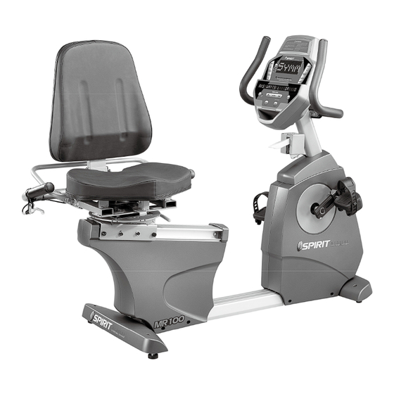
- Page 1 MR100 Rehabilitation Recumbent Bike USER’S MANUAL PLEASE READ THIS ENTIRE MANUAL CAREFULLY BEFORE OPERATING YOUR NEW LOWER BODY ERGOMETER AND SAVE IT FOR FUTURE USE.
-
Page 2: Table Of Contents
Table of Contents Product Registration…………………………………………………………………………. Important Safety Instructions………………………………………………………………… Important Electrical Information……………………………………………………………… Important Operation Instructions…………………………………………………………….. Features……………………………………………………………………………………….. Operation of Your New Bike…………………………………………………………….…… MR100 Assembly Instructions………………………………………………………………. MR100 Exploded View Drawing……………………………………………………………… 31 MR100 Parts List……………………………………………………………………………… Maintenance…………………………………………………………………………………… Specifications………………………………………………………………………………….. Guidance and manufacturer’s declaration – electromagnetic compatibility…………….. Manufacturer’s Limited Warranty…………………………………………………………….. -
Page 3: Product Registration
Thank you for your recent purchase of this high quality lower body ergometer, the MR100, from Dyaco Canada Inc. Your new product was manufactured by one of the leading fitness and medical products manufacturers in the world. Further, it is backed by one of the most comprehensive warranties in the industry. -
Page 4: Important Safety Instructions
Do not attempt to use your bike for any purpose other than for the purpose it is intended. The pulse sensors are not medical devices. Various factors, including the user’s movement, may affect the accuracy of heart rate readings. The pulse sensors are intended only as exercise aids in determining heart rate trends in general. -
Page 5: Important Electrical Information
NEVER use your bike during an electrical storm. Surges may occur in your facility ● power supply that could damage the bike’s components. All users should have medical clearance before starting any rigorous exercise ● program. This is especially important for persons with a history of heart disease or other high risk factors. - Page 6 *Heart rate measurements are not for medical use: “The heart rate function on this product is not a medical device. While heart rate grips or a thumb pulse sensor can provide a relative estimation of your actual heart rate, they should not be relied on when accurate readings are necessary.
-
Page 7: Features
8. Seat Fore/Aft Adjustment 9. Leveling Glide The Spirit MR100 is an easy product to set up and use, from the adjustments to the intuitive interface. This section explains how to set up, adjust and operate your MR100 from Spirit Medical Systems Group. - Page 8 Connecting to A.C. Power: The MR100 has a built-in universal power supply. You can plug the MR100 into any A.C. • power source from 90 to 240 volts, 50 to 60 Hz. The A.C. input is located in the front of the unit.
-
Page 9: Operation Of Your New Bike
MR100 Electronic Console: DOT MATRIX DISPLAY RPM SCALE ISOKINETICS ONLY CHANGE GRAPHIC DISPLAY PROGRAM KEYS PROGRAM KEYS SET UP MESSAGE WINDOW CHANGE DATA DISPLAYED FUNCTION KEYS Power on When initially powered on the console will perform an internal self-test. During this time all the lights will turn on for a short time. -
Page 10: Console Operation
Console Operation: 1. Set Up The Set Up key function will allow you to enter patient data, set seat and pedal adjustments for various knee ranges of motion and customize the settings of the MR100. When the Set Up key is pressed the first option in the menu appears. -
Page 11: Quick Start
2. Quick Start This is the quickest way to start an exercise session. After the console powers up you just press the Start key to begin; this will initiate the Quick Start mode. In Quick Start, the Time will count up from zero, all workout data will start to accrue and the workload may be adjusted manually by pressing the Up or Down key. -
Page 12: Preset Programs
4. Selecting and customizing programs When you enter a program you have the option of modifying the settings. If you want to begin without entering new settings just press the Start key. This will bypass the programming of data and take you directly to the start of the program. If you want to change the settings just follow the instructions in the message window. - Page 13 HILL The Hill program simulates going up and down a hill. The resistance in the pedals will steadily increase and then decrease during the program. PLATEAU The Plateau program provides a steady state exercise with warm up and cool down periods. Interval The Interval program takes you through high levels of intensity followed by periods of low intensity.
- Page 14 key. You can also go back and modify your settings by pressing the Enter key. NOTE: At any time during the editing of Data you can press the Stop key to go back one level, or screen. 5. During the Manual program you will be able to scroll through the data in the message window by pressing the Display key.
- Page 15 Vo2 Test The Vo2 program is based on the YMCA protocol and is a sub-maximal test that uses pre-determined, fixed work levels that are determined based on the heart rate readings measured as the test progresses. The test will take anywhere between 6 to 15 minutes to complete, depending on the fitness level of the user.
- Page 16 VO2 test programming: 1. Press the Vo2 button and press enter. 2. The message window will prompt you to enter your Gender. Use the Up and Down keys to change and press the Enter key to accept and proceed on to the next screen. 3.
- Page 17 What the score means: VO2max Chart for males and very fit females 18-25 26-35 36-45 46-55 56-65 years years years years years years excellent >60 >56 >51 >45 >41 >37 good 52-60 49-56 43-51 39-45 36-41 33-37 above average 47-51 43-48 39-42 35-38...
- Page 18 Constant Power The Constant Power program automatically controls the resistance level at the pedals, depending on user speed, to maintain a steady power workload. 1. Press the Constant Power key then press the Enter key. 2. The message window will prompt you to enter the Time for the program. You may enter the time using the Up and Down keys or the numeric key pad then press the Enter key to accept and proceed to the next screen.
- Page 19 Symmetry The Symmetry program may aid in achieving a more balanced pedaling stroke for patients with lower limb deficiencies, such as stroke patients and post-op knee patients. The program will measure the left and right power around the pedal rotation and display the watt measurements in the message window.
- Page 20 Using a Heart Rate Transmitter *NOTE: The chest strap transmitter is not a standard part, but is a separate purchase. How to wear your wireless chest strap transmitter: 1. Attach the transmitter to the elastic strap using the locking parts. 2.
- Page 21 Heart Rate Program operation To start the HR program follow the instructions below or just press the HR key then the Enter button and follow the directions in the message window. 1. Press the HR key then press the Enter key. 2.
-
Page 22: Mr100 Assembly Instructions
ASSEMBLY INSTRUCTIONS FOR MR100 1) Hardware STEP 1. #65- 3/8" × 2- 1/4" (4PCS) #77- 3/8" × 3/4" (6PCS) #71- 3/8" × 2" (4PCS) #84- 3/8" × 1" (4PCS) #175- 3/8" × 2-3/4" (2PCS) #205- 8.5mm × 26mm (2PCS) #208- 5/16" ×1-1/4" (1PC) #89- 3/8"... - Page 23 STEP 2. #216- M6 × P1.0 (2PCS) #221- M6 × P1.0 × 40L (2PCS) #83- 5/16" × 3/4" (4PCS) STEP 3. #136- M5 × 20L (4PCS) #220- 3/8" × 1-3/4" (2PCS) #215- 3/8" (2PCS) #206- 10mm × 25mm (2PCS) Customer Service 1-888-707-1880 Dyaco Canada Inc.
- Page 24 STEP 4. #68- 5/16" × 5/8" (8PCS) #82- 5/16" (2PCS) #76- 5/16" × 3/4" (6PCS) #83- 5/16" × 3/4" (2PCS) #187- M4 × 5L (4PCS) #98- M6 × 15L (2PCS) STEP 5. #99- M5 × 12L (8PCS) #222- M6 × 25L (4PCS) Customer Service 1-888-707-1880 Dyaco Canada Inc.
- Page 25 2) Tools #112- 12.14m/m Open wrench (1PC) #114- Phillips Head Screw Driver (1PC) #132- 14.15m/m Open wrench (1PC) #200- 5m/m L Allen Wrench (1PC) Customer Service 1-888-707-1880 Dyaco Canada Inc. 2015 Email: customerservice@dyaco.ca...
- Page 26 #283- 8m/m L Allen Wrench (1PC) #201- Short Phillips Head Screw Driver (1PC) #284- 13.14m/m Open wrench (1PC) #280- 10m/m Wrench_single (1PC) Customer Service 1-888-707-1880 Dyaco Canada Inc. 2015 Email: customerservice@dyaco.ca...
- Page 27 3) Assembly IMPORTANT NOTE: Read each step’s instructions and study the drawing carefully to become familiar with all the parts and procedures before beginning each step. STEP 1: REAR STABILIZER AND HANDLE BAR ASSEMBLY 1. Install the Rear Stabilizer (7) onto the Main Frame (1) with the four 3/8” x 2-1/4” Hex Head Bolts (65) and four 3/8”...
- Page 28 STEP 2: SWIVEL SEAT RELEASE HANDLE ASSEMBLY 1. Install the swivel seat release handle (40) onto the mating flat area of the solid round bars and secure with the two M6 x 40mm bolts (221), four curved washers (83) and two M6 nuts (216). Customer Service 1-888-707-1880 Dyaco Canada Inc.
- Page 29 STEP 3: SEAT BACK AND COVER ASSEMBLY 1. Slide the seat back assembly (5) into the seat back angle adjustment bracket and secure with the two 3/8” x 1-3/4” bolts (220), 3/8” washers (206) and 3/8” nuts (215). 2. Install the seat back cover (128) onto the seat back assembly (5) with four M5 x 20mm screws (136).
- Page 30 STEP 4: CONSOLE MAST, BRAKE LEVER AND HANDLE BAR ASSEMBLY 1. Locate the console mast cover (31) and route the computer and hand pulse cables (266, 269, 272) and the brake lever & cable (246) through the cover. Temporarily place the cover down on the main body of the bike.
- Page 31 STEP 5: CONSOLE, SEAT, PEDALS AND COVERS ASSEMBLY 1. Install the front and rear stabilizer covers (32 & 37) with the four 5mm screws (99). 2. Install the seat cushion (61) with the four M6 x 25mm bolts (222). 3. Plug in all the connectors in their mating sockets in the back of the console. Install the console onto the mounting plate and secure with the four 5mm screws (99).
-
Page 32: Mr100 Exploded View Drawing
MR100 Exploded View Drawing Customer Service 1-888-707-1880 Dyaco Canada Inc. 2015 Email: customerservice@dyaco.ca... -
Page 33: Mr100 Parts List
MR100 Parts List Item Part Number Description CC010052-R4 Main Frame CC020043-R4 Console Mast CC030033-R4 Handle Bar, Front CC040039-Z3 Seat Carriage CC040038-R4 Seat Back Bracket CC030054-R4 Handle Bar, Rear CC050001-R4 Rear Stabilizer CC060017-Z3 Seat Wheel Adjustment Plate (L) CC060018-Z3 Seat Wheel Adjustment Plate (R) CC060063-R4 Bracket, Idler Assembly C030026-Z2... - Page 34 C144001-R4 Adjusting Lever E060096-01 Power Cord K056004-A1 6004_Bearing, Crank K056203-A1 6203_Bearing, Idler N010010 Drive Belt K500055 Induction Brake N040002 Magnet, Crank Position CC060066-R4 Mechanical Brake Lever CC060071-R4 Rotation Stop, Swivel Seat CC060064-R4 Bracket, Idler Wheel Assembly (Upper) CC060065-R4 Bracket, Idler Wheel Assembly (Lower) N120024 Seat Bottom N120008...
- Page 35 J396804-Z1 3.5mm × 12mm Sheet Metal Screw K010044 Ø12.9 × 30L_Spring J020507-Z1 5/16" × 1-3/4" Button Head Socket Bolt J396807-Z1 3.5mm × 20mm Sheet Metal Screw J129021-Z1 3/8" × 7T Nut J341008-Z1 3/8" × 2" Flat Head Socket Bolt J562001-Z1 M5 ×...
- Page 36 J092004-Z1 M5 × 20mm Phillips Head Screw J310003-Z4 10mm C-Clip J210011-Z1 17mm × 23.5mm Flat Washer J210006-Z1 5mm × 12mm Flat Washer J210052-Z1 6.5mm × 25mm × 1.5T Flat Washer J129621-Z1 M6 × P1.0 × 5.0T Nut J240005 10mm × 24mm × 3T Nylon Washer J330038 M5 Allen Wrench J330007-Z1...
- Page 37 P060219-A7 Release Lever, Mechanical Brake K010002 Torsion-Spring K040001 Lever, Mechanical Brake P270055 Torsion Spring, Mech. Brake K020067 Lever, Seat Back Angle K020008-Y3 Steel Cable(84.5×76cm) E011207-01 800m/m_Wire Brake Coil Harness(Red) E011207-02 950m/m_Wire Brake Coil Harness(Red) F030420-01 1300m/m_Sensor W/Cable E020267-01 1950m/m_Computer Cable E011552 350m/m_Connecting Wire, Adaptor Power Cord E011501-01...
- Page 38 P040071-A1 HGP Wire Grommet J260008-Z2 Split Washer E040200 Ground Wire (450mm,14AWG) Customer Service 1-888-707-1880 Dyaco Canada Inc. 2015 Email: customerservice@dyaco.ca...
-
Page 39: Maintenance
Maintenance: 1. Wipe down all areas in the sweat path with a damp cloth after each use to prevent rust. 2. Check the pedal to make sure they are tight (monthly). 3. If a squeak, thump, clicking or rough feeling develops the main cause is most likely one of two reasons: 1) The hardware was not sufficiently tightened during assembly. -
Page 40: Specifications
crank rotation which we use to determine crank position. 2. MW will show: ANGLE 0 REED 0 a. When sensors operate correctly: rotate the crank and the Angle reading will show pedal RPM measurement and the Reed will change from 0 to 1 once per pedal revolution. iii. -
Page 41: Guidance And Manufacturer's Declaration - Electromagnetic Compatibility
Guidance and manufacturer’s declaration – electromagnetic compatibility The MR100 is intended for use in the electromagnetic environment specified below. The customer or the user of the MR100 should assure that it is used in such an environment. Emissions test Compliance Electromagnetic environment –... - Page 42 Immunity test IEC 60601 Compliance level – Electromagnetic environment test level guidance Electrical fast +/-2 kV for power supply +/-2 kV for power supply Mains power quality should be that of a typical transient/burst lines lines commercial or hospital environment. IEC 61000-4-4 +/-1 kV for input/output +/-1 kV for input/output lines...
-
Page 43: Manufacturer's Limited Warranty
Manufacturer’s Limited Warranty Dyaco Canada Inc. warrants all it’s bike parts for a period of time listed below, from the date of retail sale, as determined by a sales receipt or in the absence of a sales receipt. Dyaco Canada Inc.’s responsibilities include providing new or remanufactured parts, at Dyaco Canada Inc.’s option, and technical support to our independent dealers and servicing organizations. - Page 44 Please visit us online for information about our other brands and products manufactured and distributed by Dyaco Canada Inc. www.dyaco.ca www.dyaco.ca www.dyaco.ca www.dyaco.ca www.spiritfitnesscanada.ca www.spiritfitnesscanada.ca www.dyaco.ca www.dyaco.ca www.solefitness.ca www.trainorsports.ca www.dyaco.ca www.dyaco.ca www.xterrafitness.ca www.dyaco.ca Customer Service 1-888-707-1880 Dyaco Canada Inc. 2015 Email: customerservice@dyaco.ca...
Need help?
Do you have a question about the Spirit MR100 and is the answer not in the manual?
Questions and answers