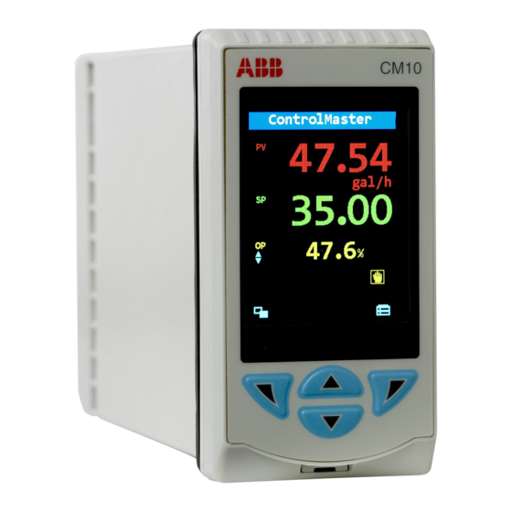
ABB ControlMaster CM10 Communications Supplement
Universal process controllers and indicators, 1/8, 1/4 and 1/2 din
Hide thumbs
Also See for ControlMaster CM10:
- User manual (128 pages) ,
- Manual (34 pages) ,
- Commissioning instructions (28 pages)

Related Manuals for ABB ControlMaster CM10


Summary of Contents for ABB ControlMaster CM10
- Page 1 Communications Supplement IM/CM/C–EN ControlMaster CM10, CM15, CM30 and CM50 Universal process controllers and indicators,...
- Page 2 We are an established world force in the design and manufacture of instrumentation for industrial process control, flow measurement, gas and liquid analysis and environmental applications. As a part of ABB, a world leader in process automation technology, we offer customers application expertise, service and support worldwide.
-
Page 3: Table Of Contents
ControlMaster CM10, CM15, CM30 and CM50 Universal process controllers and indicators, Contents Contents 1 Safety ................2 5.7 Input Coils – Digital Inputs ........18 5.8 Output Coils ............19 1.1 Electrical Safety ........... 2 5.9 Input Registers ........... 20 1.2 Symbols .............. -
Page 4: Safety
ControlMaster CM10, CM15, CM30 and CM50 Universal process controllers and indicators, 1 Safety 1 Safety Information in this manual is intended only to assist our customers in the efficient operation of our equipment. Use of this manual for any other purpose is specifically prohibited and its contents are not to be reproduced in full or part without prior approval of the Technical Publications Department. -
Page 5: Health & Safety
ControlMaster CM10, CM15, CM30 and CM50 Universal process controllers and indicators, 1 Safety 1.3 Health & Safety Health and Safety To ensure that our products are safe and without risk to health, the following points must be noted: The relevant sections of these instructions must be read carefully before proceeding. -
Page 6: Introduction
ControlMaster CM10, CM15, CM30 and CM50 Universal process controllers and indicators, 2 Introduction 2 Introduction This manual provides details for the ControlMaster CM10 ( DIN), CM15 ( DIN), CM30 ( DIN) and CM50 ( DIN) communication protocols, MODBUS connections and configuration tables and Ethernet connection details. -
Page 7: Communication Overview
ControlMaster CM10, CM15, CM30 and CM50 Universal process controllers and indicators, 3 Communication Overview 3 Communication Overview Extensive communication options enable the ControlMaster to be integrated into larger control systems easily or connected to other process instrumentation. 3.1 Communication Options 3.1.1 Ethernet... -
Page 8: Rs 485 Modbus
ControlMaster CM10, CM15, CM30 and CM50 Universal process controllers and indicators, 3 Communication Overview Fig. 3.2 ControlMasters connected to a ScreenMaster Fig. 3.1 Webserver 3.1.2 RS 485 MODBUS Using RS 485 MODBUS, values and status can be communicated to and from the controller in real-time via an RS 485 connection. -
Page 9: Pc Configuration
ControlMaster CM10, CM15, CM30 and CM50 Universal process controllers and indicators, 3 Communication Overview 3.2 PC Configuration In addition to configuration via the front panel, the ControlMaster can be configured from a PC via the infrared port (configuration files can be stored locally on a PC and transferred to the controller via the infrared port). -
Page 10: Communication Level
ControlMaster CM10, CM15, CM30 and CM50 Universal process controllers and indicators, 4 Communication Level 4 Communication Level 4.1 Communication The Communication parameters are accessed from the Advanced access level – refer to the User Guide supplied with your instrument for access details. - Page 11 ControlMaster CM10, CM15, CM30 and CM50 Universal process controllers and indicators, 4 Communication Level …Communication RS485 Setup Mode Selects the MODBUS serial communication serial link as 2 Wire, 4 Wire or Off – see Section 5.3, page 15. Baud Rate A selectable communication transfer rate up to 115.2 K baud (bits per second) maximum (default...
- Page 12 ControlMaster CM10, CM15, CM30 and CM50 Universal process controllers and indicators, 4 Communication Level …Communication MODBUS TCP Note. After changing any of the TCP parameters it is advisable to power-cycle the instrument to Setup ensure changes are applied. Implementation Select the MODBUS TCP operation mode: ...
- Page 13 ControlMaster CM10, CM15, CM30 and CM50 Universal process controllers and indicators, 4 Communication Level …Communication Ethernet DHCP Set DHCP (Dynamic Host Control Protocol) enable to On if the IP address is to be allocated dynamically by the network. Set to Off if the IP address is defined statically.
- Page 14 ControlMaster CM10, CM15, CM30 and CM50 Universal process controllers and indicators, 4 Communication Level …Communication Email SMTP Server IP The IP (Internet Protocol) address of the SMTP (Simple Mail Transport Protocol) server used to distribute emails. Recipients Email Address 1(3) Enter the email address(es) of the recipient(s).
-
Page 15: Modbus Communications
ControlMaster CM10, CM15, CM30 and CM50 Universal process controllers and indicators, 5 MODBUS Communications 5 MODBUS Communications 5.1 Electrical Connections This section describes the connection of serial data cables between the master (host computer) and slave instrument on a MODBUS serial link. - Page 16 ControlMaster CM10, CM15, CM30 and CM50 Universal process controllers and indicators, 5 MODBUS Communications Warning. The instrument is not fitted with a switch therefore a disconnecting device such as a switch or circuit breaker conforming to local safety standards must be fitted to the final installation.
-
Page 17: Two-Wire And Four-Wire Connection
ControlMaster CM10, CM15, CM30 and CM50 Universal process controllers and indicators, 5 MODBUS Communications 5.3 Two-wire and Four-wire Connection MODBUS serial communications can be configured as either 2-wire or 4-wire serial links – see Fig. 5.1. The instrument must be added to the link configuration on the host system – refer to information supplied with the host system. -
Page 18: Pull-Up And Pull-Down Resistors
ControlMaster CM10, CM15, CM30 and CM50 Universal process controllers and indicators, 5 MODBUS Communications 5.4 Pull-up and Pull-down Resistors To prevent false triggering of slaves when the master (host computer) is inactive, pull-up and pull-down resistors must be fitted to the RS422/485 interface in the host computer. -
Page 19: Serial Connections
ControlMaster CM10, CM15, CM30 and CM50 Universal process controllers and indicators, 5 MODBUS Communications 5.6 Serial Connections Connections to the MODBUS serial board must be made as shown in Fig. 5.1. Connections to two- or four-wire link configurations on systems with multiple slaves must be made in parallel as shown in Fig. 5.2. When connecting cable screens, ensure that ground loops are not introduced. -
Page 20: Input Coils - Digital Inputs
ControlMaster CM10, CM15, CM30 and CM50 Universal process controllers and indicators, 5 MODBUS Communications 5.7 Input Coils – Digital Inputs MODBUS Title MODBUS Title Coil Coil Analog Input 1 Fail Loop 2 Setpoint 3 Active Analog Input 2 Fail Loop 1 Setpoint 4 Active... -
Page 21: Output Coils
ControlMaster CM10, CM15, CM30 and CM50 Universal process controllers and indicators, 5 MODBUS Communications MODBUS Title MODBUS Title Coil Coil Logic Equation 7 State Loop Break 2 State Logic Equation 8 State Delay Timer 1 State Realtime Alarm 1 State... -
Page 22: Input Registers
ControlMaster CM10, CM15, CM30 and CM50 Universal process controllers and indicators, 5 MODBUS Communications 5.9 Input Registers MODBUS Title Register 5.9.1 Read-only 32 Bits 5030 Loop 2 Deviation MODBUS Title 5032 Loop 1 Feedforward Value Register 5034 Loop 2 Feedforward Value... -
Page 23: Input Registers For Bytes
ControlMaster CM10, CM15, CM30 and CM50 Universal process controllers and indicators, 5 MODBUS Communications 5.10 Holding Registers MODBUS Title Register 5.10.1 Writable 16 Bits 5078 Volume 2 MODBUS Title 5080 Custom Linearizer 1 Value Register 5082 Custom Linearizer 2 Value... -
Page 24: Writable 32 Bits
ControlMaster CM10, CM15, CM30 and CM50 Universal process controllers and indicators, 5 MODBUS Communications 5.10.2 Writable 32 Bits MODBUS Title Register MODBUS Title 6606 Alarm 5 Trip Register 6608 Alarm 5 Hysteresis 6000 Totalizer 1 Preset Value 6610 Alarm 6 Trip... - Page 25 ControlMaster CM10, CM15, CM30 and CM50 Universal process controllers and indicators, 5 MODBUS Communications MODBUS Title MODBUS Title Register Register 6718 Loop 2 Output 1 Cycle Time 6794 Loop 1 Derivative Time 3 6720 Loop 2 Output 2 Cycle Time...
-
Page 26: Ethernet Connections
ControlMaster CM10, CM15, CM30 and CM50 Universal process controllers and indicators, 6 Ethernet Connections 6 Ethernet Connections Standard Connections Ethernet Adaptor Rear CM50 Rear to Terminal CM10 View View Connections CM15 CM30 Remove existing terminal screws and screw the Ethernet adaptor... -
Page 27: Specification
ControlMaster CM10, CM15, CM30 and CM50 Universal process controllers and indicators, 7 Specification 7 Specification Communications MODBUS RTU (optional) Baud rate up to 115 k Baud Note. Only 1 optional communications board can be fitted per Isolation galvanically isolated from the rest of the controller. - Page 28 ControlMaster CM10, CM15, CM30 and CM50 Universal process controllers and indicators, 7 Specification IM/CM/C–EN...
- Page 29 Customer Support We provide a comprehensive after sales service via a Worldwide Service Organization. Contact one of the following offices for details on your nearest Service and Repair Centre. ABB Limited Tel: +44 (0)1480 475321 Fax: +44 (0)1480 217948 ABB Inc.
- Page 30 Contact us To find your local ABB contact visit: Note www.abb.com/contacts We reserve the right to make technical changes or modify the contents of this For more product information visit: document without prior notice. With www.abb.com regard to purchase orders, the agreed particulars shall prevail.
Need help?
Do you have a question about the ControlMaster CM10 and is the answer not in the manual?
Questions and answers