Table of Contents
Advertisement
Advertisement
Table of Contents

Summary of Contents for Quest Engineering QSR1000
- Page 1 QSR1000 AM/FM STEREO RECEIVER INSTRUCTIONAL MANUAL...
- Page 2 FEDERAL COMMUNICATIONS COMMISSION (FCC) INFORMATION This device generates and uses radio frequency (RF) energy, and if not installed and used properly, this equipment may cause interference to radio and television reception. If this equipment does cause interference to radio or television reception (which you can determine by turn- ing the equipment off and on), try to correct the interference by one or more of the following measures: •...
-
Page 3: Table Of Contents
FIRST THING FIRST UNPACK THE RECEIVER......................4 BASIC CONNECTIONS........................4 SYSTEM SETUP.........................5 CONNECTING THE WIRES........................5 CONNECTING THE MAIN SPEAKERS....................5 CONNECTING THE ANTENNAS......................5 CONNECTING FOR POWER....................6 USING HEADPHONES......................6 RECEIVER CONTROLS & OPERATIONS GENERAL CONTROLS......................7 DISPLAY MESSAGES.........................8 TUNING THE RECEIVER......................8 TO STORE STATION...........................9 TO PLAY PRESET STATION........................9 PRESET SCANNING...........................9 TUNER-30 PRESET SCAN........................9 SELECT PRESET MEMORY........................9... -
Page 4: First Thing First
FIRST THINGS FIRST UNPACK THE RECEIVER Unpack the receiver and locate all the accessories. You should have: • one receiver unit • one remote control • one external, detachable FM T-type antenna • one external AM loop antenna • one instruction book BASIC CONNECTIONS Assuming you have a VCR, the following steps will help you quickly set up your new receiver. -
Page 5: System Setup
FIRST THINGS FIRST SYSTEM SETUP CONNECTING THE WIRES Each speaker -the two main, -has a designated set of terminals on the back panel of the central unit. Uncoil the speaker wires and locate the bare ends. Press and hold down on the tab to open the red terminal, then insert the red (+) wire. -
Page 6: Connecting For Power
FIRST THINGS FIRST CONNECTING FOR POWER Make sure you connect all your other electronic components and your speakers before plugging your receiver into the outlet. Plug the power cord in the wall outlet, matching the wide blade of the plug with the wide slot in the outlet. Be sure to insert the plug completely. -
Page 7: Receiver Controls & Operations
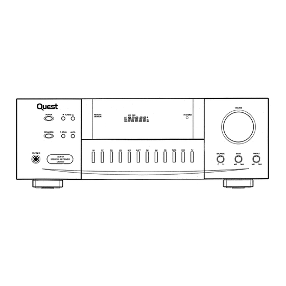
RECEIVER CONTROLS & OPERATIONS GENERAL CONTROLS POWER STAND BY/ON BALANCE The BALANCE dial allows you to manually adjust The POWER STANDBY/ON button activates or the balance of sound coming from your speakers. deactivates the system. When the system is activat- ed, the unit will default to the last mode it was in BASS before power was removed. -
Page 8: Display Messages
RECEIVER CONTROLS & OPERATIONS DISPLAY MESSAGES The following is an example of all the display messages you may encounter while using your receiver. Specific messages are referenced within the section(s) they apply. TUNING THE RECEIVER SELECT THE AM/FM BAND AUTO TUNING 1. -
Page 9: To Store Station
RECEIVER CONTROLS & OPERATIONS TUNER-30 PRESET SCAN TO STORE A STATION SELECT PRESET 1. Press the FM or AM button on the receiver (or the AM-FM button on the remote). 1. Select 1-5 Preset Station • You can select the 1-5 preset scan directly & use 2. -
Page 10: Connecting Auxiliary Components
CONNECTING AUXILARY COMPONENTS BEFORE YOU CONNECT.. CONNECTING THE CABLES • Protect components from power surges. • Try not to coil any power cables and keep them away from the audio/video cables as much as • Connect all components before plugging power possible. -
Page 11: Connecting A Compact Disc
CONNECTING AUXILARY COMPONENTS CONNECTING A COMPACT DISC PLAYER Using one paired (red/white) stereo cable, connect your new receiver to your compact disc player as shown to the right. To play a CD, press CD, put the receiver in CD mode and press PLAY. -
Page 12: Using The Remote Control
USING THE REMOTE CONTROL BATTERY INSTALLATION The remote control operates on two batteries. Install them before attempting to operate the remote. 1. Slide the battery compartment cover off the back of the remote. 2. Insert 2 AAA batteries, matching the + and - ends of each battery with the symbols in the compartment. -
Page 13: Care And Maintenance
CARE AND MAINTENANCE TROUBLESHOOTING TIPS RECEIVER/TUNER OPERATION GENERAL No audio. STEREO indicator is off. • Adjust the antenna. • Make sure the MUTE inclicator on the front panel is off. • The signal is too weak. Connect an external • Make sure the speakers are turned on. antenna •... -
Page 14: Equipment Specifications
EQUIPMENT SPECIFICATIONS AMPLIFIER SECTION Left & Right Channel: 100Watts 1% THD @ 1KHz Muting Attenuation: 90 dB Frequency Response: 80 - 10 KHz +/- 3 dB AM TUNER SECTION Frequency Response: 8OHz - 2.3KHz +/- 6 clB Usable Sensitiivity: 800 uV/m @: S/N 20 dB Signal to Noise: 38 dB Image Ratio: 30 dB ~ 1000 KHz IF Rejection: 40 dB... -
Page 15: Limited Warranty
LIMITED WARRANTY Quest warrants this product to be free from manufacturing defects in material and workmanship under normal use for a period of 1 year from date of purchase, if service is required during the first year of ownership, product should de returned to the store where it was purchased with the original receipt for an exchange. -
Page 16: Important Safety Instructions
IMPORTANT SAFETY INSTRUCTIONS Some of the following information may not apply to your particular product; however, as with any electronic product, precautions should be observed during hanlding and use. • • Carts and Sands - The appliance should be used only with a cart that is Before using the product, please follow and adhere to all warnings, recommended by the manufacturer.
Need help?
Do you have a question about the QSR1000 and is the answer not in the manual?
Questions and answers