Table of Contents
Advertisement
Quick Links
Advertisement
Table of Contents

Related Manuals for Waldorf KB 37


Summary of Contents for Waldorf KB 37
- Page 1 KB37 U ALDORF ANUAL Waldorf Music GmbH 2016-09-21...
- Page 2 Bacaj, Daniel Krawietz, Kurt ”Lu” Wangard, Echo Wu, Miroslaw ”Mirek” Pindus, Thomas Brenner, Isabelle Kernhof, Roger Keller, Markus Erdmann, Holger Waldorf Music GmbH is not liable for any erroneous information contained in Steinbrink, Christian Gritzner, Mic Irmer, Victor H ¨ oller this manual.
-
Page 3: Table Of Contents
CONTENTS CONTENTS Contents 8 Arpeggiator 8.1 Switching on/off ......8.2 Play Parameters ......1 General Safety Guidelines 8.2.1 Clock . -
Page 4: General Safety Guidelines
This device is designed exclusively to generate low frequency audio signals for sound generation. Any other use is prohibited and voids the warranty ex- tended by Waldorf Music GmbH. Damages due to incorrect use are not the responsability of Waldorf Music GmbH. -
Page 5: Device Maintenance
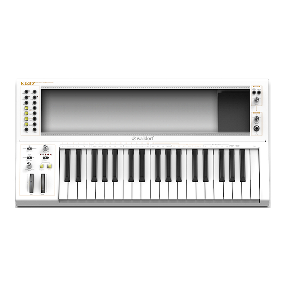
4 DEVICE OVERVIEW 2 Device Maintenance 4 Device Overview Refer all service and repair tasks to qualified personnel. 4.1 Module Frame with Bus Backplane Use only a soft cloth or brush to clean the device surface. The module frame is the place where you mount your modules. Inside the frame there is a backplane with pin headers to connect the modules to the A-100 bus. -
Page 6: Cv Panel
4.2 CV Panel 4 DEVICE OVERVIEW 4.2 CV Panel Gate output triggered on each note The CV panel on the left side of the unit provides jacks to access all control Pitch CV output 1V/octave (level 0..+7V) voltages as well as some illuminated buttons to set some configurations. Clock output for syncing (generates a pulse on each clock signal) Reset output (generates a pulse when a MIDI Stop mes-... -
Page 7: Audio Panel
4 DEVICE OVERVIEW 4.3 Audio Panel 4.3 Audio Panel 4.4 Controls Panel The audio panel on the right side of the unit is where you connect the output The controls panel provides access to various functions of the KB37. You can signals of your modules and set the volume for the main outputs and the head- set the behaviour of the CV/Gate generation or enable/disable the arpeggiator. -
Page 8: Back Panel
4.5 Back Panel 5 CONNECTIONS 5 Connections 4.5 Back Panel The back panel provides the connectivity needed to integrate the KB37 into 5.1 Power your setup. An AC power outlet is needed to power up your KB37. Make sure that the power switch on the back panel is turned off before you connect your unit. -
Page 9: Midi
6 ATTACHING MODULES 5.3 MIDI 6 Attaching Modules Before connecting and disconnecting the KB37 from a power supply source, turn your amp’s volume control all the way down to avoid damage due to on/off Before connecting modules, make sure that the KB37 is turned off. Please also switching noise. -
Page 10: Cv/Gate Interface
7 CV/GATE INTERFACE 7 CV/Gate Interface 7.2 Pitch The Pitch output delivers a signal according to the calculated note pitch and The CV/Gate interface features various output jacks on the left side of the has a 1V/octave scaling. The maximum output level is +7V. When calculating KB37. -
Page 11: Reset
7 CV/GATE INTERFACE 7.4 Reset 7.4 Reset second voice that can be patched to a separate oscillator. The Reset output delivers a short +5V trigger pulse each time a MIDI Stop event This is how you enable/disable the output for Pitch 2: is received. -
Page 12: Bend
7.10 Bend 8 ARPEGGIATOR 8 Arpeggiator 7.10 Bend The Bend output delivers a bipolar signal in the range -5V..+5V according to the The arpeggiator splits up chords played on the keyboard or via incoming MIDI MIDI Pitch Bend 14-bit value. messages into single notes and plays them as a sequence. -
Page 13: Clock
8 ARPEGGIATOR 8.3 Setting the Tempo 8.2.3 Octave Range 8.2.1 Clock Determines the range of the single notes in octaves. When it is set to 1, the Select the note value for the steps between 1/2, 1/4, 1/8, 1/16 and 1/32 notes. note list will be played back in the same octave as originally entered. -
Page 14: Hold Mode
8.5 Sending Generated Notes over MIDI 8 ARPEGGIATOR 8.4.1 Hold Mode Parameter Value range In hold mode the arpeggio changes every time a new chord is played. A chord Enable change is detected when new notes arrive after all previous ones are released. Hold The hold mode can be activated or deactivated on the control panel: Clock... -
Page 15: Setup Functions
9 SETUP FUNCTIONS 9 Setup Functions 9.1.2 Source This setting determines if the clock for the arpeggiator and the Clock output is The setup functions are used to access the KB37’s configuration settings. Most derived from the internal clock generator or externally. When Auto is selected, of these settings are memorized permanently when the unit is switched off. -
Page 16: Local Control
9.3 Pitch Bend Range 9 SETUP FUNCTIONS printed as secondary labels in a lighter color on the lower part of the keyboard. This parameter determines the amount of modulation that is applied to the Pitch output of the CV interface when using the Pitch Wheel. Label Description Default... -
Page 17: Panic
10 SENSORS 9.6 Panic 10 Sensors a wheel’s value reaches its limit way to early Checking the wheels’ values should be done by looking at the generated MIDI The KB37 features a Sensor input on the back panel that can be used to at- messages. -
Page 18: Example Circuits
10.3 Example Circuits 10 SENSORS 10.3.2 Touch Sensor This circuit can be used to convert skin resistance to a control voltage. You may want to vary R1 to adjust the sensitivity. The capacity C1 is intended for filtering since your body will probably pick up more noise than desired. 10.3 Example Circuits 10.3.3 Microphone Below you’ll find some example circuits that can be attached to the sensor input. -
Page 19: Distance Sensor
11 FIRMWARE UPDATE 11 Firmware Update 10.3.4 Distance Sensor The unit’s internal firmware can be updated over USB. To perform this opera- tion, the KB37 has to be put in bootloader mode at startup. Then the firmware file has to be send via MIDI SysEx from your computer. This is how you update the firmware: Switch off the unit in case it is powered on Press and hold the Setup button on the controls panel... -
Page 20: Factory Reset
13 TROUBLESHOOTING 12 Factory Reset 13 Troubleshooting In case you fully messed up the configuration of your KB37 or you want to reset 13.1 Modules power fail it to a clean state, you can do a factory reset of all stored parameters. Check the orientation of the pin headers on your modules This is how you do the factory reset: Check if the total power consumption of all modules is within the KB37’s... - Page 21 14 SPECIFICATIONS 14 Specifications 14.1 Power Supply Input Voltage: 110/220V AC (switchable at PSU) Power Consumption: 10W (idle, no modules attached) Bus Power: +12V/1.5A, -12V/1.5A 14.2 Dimensions and Weight Width: 656mm Depth: 334mm Height: 122mm Total Weight: 8.5kg Module Frame Width: 543mm (107 HP)
Need help?
Do you have a question about the KB 37 and is the answer not in the manual?
Questions and answers