
Related Manuals for RDS P332


Summary of Contents for RDS P332
- Page 1 P P P P 3 3 3 3 32 32 RDS Encoder RDS Encoder RDS Encoder RDS Encoder Technical Manual Version 2.1b Web: http://www.pira.cz/rds/ E-mail: mail@pira.cz...
-
Page 2: Table Of Contents
Installation and Setting-up ..............................7 Connection .....................................7 On-board Controls ................................8 Power Supply ..................................9 Level and Phase Adjustment ...............................9 Setting Basic RDS Data ...............................11 Dynamic PS Text ..................................14 Alternative Frequencies .................................15 Method A .....................................15 Method B ....................................16 Enhanced Other Networks information (EON) control ....................17 Weekly Scheduling.................................18... -
Page 3: Introduction
1 Introduction The P332 RDS encoder is a result of more than 10 years experience collecting and presence on the market. It is especially developed for regional and national stations but can suit for other stations as well. Depending on technical requirements, it may be used as an economical alternative to industry standard RDS encoders. -
Page 4: Technical Specifications
Output Output impedance 100 Ω Recommended load impedance > 70 Ω, < 1 nF, no DC offset Max. output voltage (RDS + MPX) 9.0 V p-p Recommended RDS level 3 - 11 % of MPX Notes: p-p - peak-to-peak value... -
Page 5: Block Diagram
3 Block Diagram Input Output SIDE/LOOP Relay Digital output level control EEPROM Pilot/MPX P132 Microcontroller Ethernet Optical Module Isolation Program Ethernet RS-232 LCD Display Socket Connector LED Indicators Analogue Part Power Digital Part Supply Ethernet Module... -
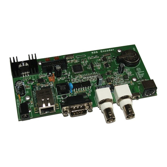
Page 6: Physical Description
2: Ground B1 - Lithium battery 3 V for real time backup. Estimated endurance is 10 years. Replace by CR2032 type. Note: EEPROM memory which is used for RDS data storage does not require any voltage to hold the data. -
Page 7: Installation And Setting-Up
The RDS signal must be fed into modulation input (added to MPX signal if stereo encoder is used). If stereo encoder is used, one of its outputs (MPX or pilot tone) must be fed into the RDS encoder input to meet the synchronization requirement. -
Page 8: On-Board Controls
J1 - MPX loopthrough switch Set the switch to LOOP position only if you want to pass the input signal to the output of the RDS encoder (loopthrough mode). In all other cases the switch must be set to SIDE position! -
Page 9: Power Supply
In terminal, using ASCII command LEVEL= The P332 RDS encoder allows direct adjusting of the RDS level in 256 steps, in range 0 to 255, by assigning a corresponding value to the LEVEL parameter. Each step represents approx. 15.6 mV increase. - Page 10 From factory the phase shift is already set to 0 degrees so user may skip this chapter. Fetch pilot or MPX signal to the RDS encoder. The PILOT LED will indicate that the pilot tone is present. Adjust right phase shift (0 or 90 degrees phase shift between 19 kHz pilot tone and 57 kHz RDS subcarrier, measured on transmitter input, see the oscillograms).
-
Page 11: Setting Basic Rds Data
Setting Basic RDS Data Before getting on-air with the RDS signal, you will need to decide on the settings to be used. The following RDS services must be set as the first. Use the Windows control software and its GUI or use the embedded website. For more experienced users or those without a Windows PC, any terminal programme can be used (see chapter 11). - Page 12 The Alternative Frequencies are used to tell receivers what frequencies they can receive the radio station on. This facility is particularly useful in the case of car and portable radios. For this to work, each transmitter must have RDS with the same PI code.
- Page 13 The status bar at the bottom of the window shows whether the data was sent successfully. If Communication Error! is shown, check the connection to the RDS encoder, its power supply and that the correct COM port is selected in the Preferences dialogue box.
-
Page 14: Dynamic Ps Text
Standard RDS enabled receiver disposes of 8-character LCD display but we usually need to show pile of information and commercials. So small display on the one hand and so much demands on the other hand. The P332 solves it by unique system of text messages showing. -
Page 15: Alternative Frequencies
To establish a common list of AF-A using a terminal: Note: Requires only one RDS encoder for entire network (common STL or one main transmitter and two repeaters). The list must contain all frequencies on which the signal from the RDS encoder is carried. -
Page 16: Method B
Method B Total capacity: up to 8 lists, up to 12 AF pairs each Method B AF coding is a more complex method that is used where the number of AFs used by a transmitter and its associated repeater stations exceed 25, or where it is required to indicate frequencies which belong to different regions which at times carry different programs. -
Page 17: Enhanced Other Networks Information (Eon) Control
EON feature will broadcast a switch signal by setting the appropriate EON TA flag to 1. The EON TA flags can be controlled by software for all four EON links in the P332. The first EON link TA flag can be also controlled by external TA/EON1TA switch. -
Page 18: Weekly Scheduling
This feature allows scheduling of text messages, program type names and any other commands in hourly, daily and weekly program. The scheduling is provided directly by the P332 unit. Once set, it works with no more support from PC or control application. This is especially useful when the RDS encoder is placed on remote site or where reliability is important. -
Page 19: Broadcast Automation System Link-Up
10 Broadcast Automation System Link-up To send dynamic data via the RDS it's very useful to link the RDS encoder with your broadcast automation system. This usually results in a possibility of sending commercials, actual song information, program announcements and more. - Page 20 To reach the best possible compatibility with broadcast automation systems, the P332 includes a special set of compatibility commands. In the systems where the P332 is not directly supported (or the system is older version) the user may try to select another RDS encoder model to send text messages. Where possible, set the communication as unidirectional.
-
Page 21: Communication Ports
11 Communication Ports 11.1 Overview For configuration and control requirements the RDS encoder is equipped with several communication ports. These ports include individual buffers and work in complete independence, i.e. all ports can be used at one time by different applications. -
Page 22: Working With A Terminal Application
This section explains how to make the settings above from a terminal application (and also from embedded web- server). All RDS encoder’s settings and configuration incl. text messages etc. can be made from a terminal using a set of ASCII commands. (Any Windows GUI based application effectively does the same; it translates the user’s data into the ASCII commands.) -
Page 23: Command Interpreter
11.3 Command Interpreter The RDS encoder command interpreter meets the following rules: Any instruction sent to the RDS encoder must be validated by <Enter>. Before validating you may correct the characters by pressing <Backspace>. There are several methods of use for the commands: Query or command without argument, ex. -
Page 24: Additional Information
11.4.1 Unidirectional or bidirectional – What is the difference? The P332 supports both unidirectional and bidirectional communication modes. Nothing is required to be set, the mode of operation results only from the method of communication. Unidirectional... - Page 25 (exec. time) ← ↓ + ← ↓ ← ↓ Legend: TX – data sent to the RDS encoder, RX – data read from the RDS encoder, ← - CR (char. 13), ↓ - LF (char. 10) 11.4.3 Useful notes ASCII char. 9 (TAB) is converted to char. 32 (space).
-
Page 26: List Of Commands
12 List of Commands 12.1 Command Summary Basic: *AF= Alternative Frequencies AFCH AFCH= *AFCH Alternative Frequency Channels Decoder Identification DPS1 DPS1= *DPS1 Dynamic PS 1 DPS1ENQ= Dynamic PS 1 Enqueue DPS2 DPS2= *DPS2 Dynamic PS 2 DPS1EN DPS1EN= *DPS1EN Dynamic PS 1 Enable DPS2EN DPS2EN= *DPS2EN... - Page 27 ECHO ECHO= *ECHO Terminal Echo EXTSYNC EXTSYNC= *EXTSYNC External Pilot Synchronization Actual IP Address LEVEL LEVEL= *LEVEL RDS Signal Level LTO= *LTO Local Time Offset MJD= Modified Julian Day PHASE PHASE= *PHASE RDS Signal Phase PILOT Pilot Tone Present RDSGEN...
- Page 28 Reading of Internet Content RTP= Radiotext Plus Tagging Data RTPRUN RTPRUN= Radiotext Plus Running Bit SETIPR SETIPR= *SETIPR= IP Registration URL SETSPY= Set RDS Monitoring Counter SHORTRT SHORTRT= *SHORTRT Short Radiotext SITE *SITE= Site Address List UDG1 UDG1= *UDG1 User Defined Groups 1...
-
Page 29: Basic Commands
Stores the AF list into EEPROM (default space for method A) Stores the AF list into EEPROM (to a space used by method B) *AF=1 Not allowed (87.5 MHz not defined in RDS standard) AF=87.5 Not allowed (108.0 MHz not defined in RDS standard) AF=108.0... - Page 30 Not allowed (0 as first digit) Program Service name Static name of radio station that is displayed on receiver. Max. 8 characters long. The PS= command requires additional processing time of up to 400 ms for internal synchronization with RDS group order. PS=KISS FM...
- Page 31 Program Type number (0-31) An identification number to be transmitted with each program item, intended to specify the current Program Type within 31 possibilities. Program type codes (Europe): 0 - (none) 16 - Weather 1 - News 17 - Finance 2 - Affairs 18 - Children 3 - Info...
- Page 32 The reason is absolutely outside the RDS encoder and comes out from the fact that scrolling PS has never been included in RDS standard. Due to this the high speed is not recommended.
- Page 33 Switching the PROGRAM causes clearing of the TA flag. Note: In some cases the RDS encoder drives the TP and TA flags automatically, especially if EON feature is enabled. This ensures that these flags are set correctly under all conditions.
- Page 34 Sets most parameters and services in actually selected Program to their default values. Does not clear Messages and Scheduling items. Does not clear port and network settings. Apply for example if new blank EEPROM is placed on the board or if the RDS encoder was previously used for another station.
-
Page 35: Eon Commands
12.3 EON Commands EONxAF EON x Frequencies (87.6-107.9) List of Other Network frequencies that can be received in the area covered by linking station. Each item is in MHz representation in range of 87.6-107.9 MHz. Up to 25 items allowed. EON1AF=98.0,99.3 Sets 98.0 and 99.3 MHz frequencies for Other Network 1 EONxAFCH... -
Page 36: Messages Commands
These commands are provided for working with the bank of text messages that is useful especially for offline operation of the RDS encoder or in conjunction with the scheduling feature. Using these commands you may enter the text messages and assign them to radiotext or dynamic PS. -
Page 37: Scheduling Commands
SxxP Scheduling Item PTY (0-31) Allows including optional Program Type information so that the Command may be used for another RDS service change. Sets the PTY to 15 (Other M) *S03P=15 *S04P= Clears (disables) the PTY option for the item 04. -
Page 38: System Commands
DATE=30.11.05 of November 2005 ECHO Terminal Echo (0, 1) Determines if the RDS encoder sends an echo (1) of each character or not (0), that it receives via the port. ECHO=1 EXTSYNC External Pilot Synchronization (0, 1) 0 - Forced internal clock source (for mono transmission) - Page 39 Disables (0) or enables (1) the RDS subcarrier generator. Does not affect any other functions. RDSGEN=0 RESET Reset Provokes a hardware reset of the RDS encoder and is equivalent to an "off-on" cycle of the RDS encoder. RESET SETCTO Connection Timeout This command is described in the document ‘P132 RDS Encoder –...
-
Page 40: Advanced Commands
12.7 Advanced Commands Encoder Address List (0-63[,0-63]) This command is described in the document ‘P132 RDS Encoder – Communication Ports and Internet Functions’. Conditional Command Executes specified command when specified condition occurs. Optional ELSE command supported. Syntax: *CC=[aa]bcc:dddddddd *CC=ELSE:eeeeeeee where is:... - Page 41 *CC= DSNx Program 1/2 Data Set Number This command is described in the document ‘P132 RDS Encoder – Communication Ports and Internet Functions’. Extended Country Code H (00-FF) Uniquely determines the country in conjunction with the first digit of PI.
- Page 42 Using this command, the RDS transmission can then be partially or fully controlled by an external application. For full RDS stream control, 9600 bps or higher com. speed should be used. Next Group can follow after previous command success characters (+). Opposite to UECP control, groups inserted via G command are not buffered.
- Page 43 This command is described in the document ‘P132 RDS Encoder – Communication Ports and Internet Functions’. PS Window Returns actual Program Service name that is being sent by the RDS encoder. The value returned is an output of internal real-time RDS decoder so it’s affected also by Dynamic PS and user defined groups. READWEB Reading of Internet Content This command is described in the document ‘P132 RDS Encoder –...
- Page 44 User Defined Groups 1 Specifies up to 8 groups in BBBBCCCCDDDD format, which are repeatedly transmitted in sequence by the RDS encoder. BBBB, CCCC and DDDD represent the contents of the block 2, block 3 and block 4 in hexadecimal expression.
-
Page 45: Memory Organization
12.8 Memory Organization Operational Mem ory (RAM ) Comm on settings, Address lists, Operating data, ... R DS Actual Program Set or 2) Output PI, PS, D ynamic PS, RT, AF, Group Sequence , ... Port 1 Port 2 C om m and Non-volatile Mem ory (EEPROM ) Interpreter Port 3... -
Page 46: Further Features
1 selects the Program set 1, the switch closure or logical 0 selects the Program set 2. Alternatively the switch input can be used for selecting a text message or for control of other RDS service or setting. For more details see chapter 12.7 - Conditional Command. -
Page 47: Internet Functions
13.9 On-line Support Not sure how to set-up the unit? Some RDS related feature is missing? Feel free to contact us via the email! Important note: Before sending an email please make sure you have read entire content of this manual (incl. section 15.4), control software help file and also forum, F.A.Q. -
Page 48: Universal Encoder Communication Protocol (Uecp)
UECP commands and functions that do not comply with the P332 concept, are rarely used or potentially insecure, are not implemented. 14.1.1 To turn-on the UECP support Configure all RDS services and settings as required. - Page 49 0: do not toggle A/B flag; 1: toggle A/B flag. The RDS encoder address list can contain up to three items for the Site address and up to three items for the Encoder address. One of these items is always fixed to 0, the remaining two items can be changed using the commands *SITE= and *ADR=.
- Page 50 UECP really ‘universal’. When the UECP is enabled, the RDS encoder accepts any mixture of ASCII commands and UECP records on the same communication port. The UECP communication is always unidirectional. There are no responses sent to the UECP records.
-
Page 51: Traffic Message Channel (Tmc) Application Notes
Notes: Any RDS group inserted using the UECP elements 24, 30, 40 or 42 is put into the UECP buffer. See section 14.1.5 for more details. For TMC transmission it is recommended to leave the UECP buffer as transparent so the TMC data providing application has full control over the TMC transmission. -
Page 52: Annexes
15.1 Character set and code-table conversions The RDS system, as defined by the standards, does not support Unicode character set. Default character set (G0) used within the RDS system is limited to the characters provided in following EBU Latin code-table. -
Page 53: Communication Protocol Implementation Flowcharts
15.2 Communication Protocol Implementation Flowcharts Following flowcharts allow the developer to implement the P332 ASCII protocol to any application easily. 15.2.1 Unidirectional Communication Send command basic flowchart (unidirectional communication). 15.2.2 Bidirectional Communication Confirm sequences definition: CS1=Chr(13)+Chr(10)+’+’+Chr(13)+Chr(10)+Chr(13)+Chr(10) CS2=Chr(13)+Chr(10)+’!’+Chr(13)+Chr(10)+Chr(13)+Chr(10) CS3=Chr(13)+Chr(10)+’-’+Chr(13)+Chr(10)+Chr(13)+Chr(10) CS4=Chr(13)+Chr(10)+’/’+Chr(13)+Chr(10)+Chr(13)+Chr(10) Variables used:... - Page 54 Send command flowchart (bidirectional communication).
- Page 55 Read value flowchart.
-
Page 56: Rds Group Format
Checkwords and offsets are always computed and inserted automatically by the RDS encoder. PI is always inserted automatically by the RDS encoder in block 1, and also in block 3 for version B of the group. Due to this the block 1 is never specified when inserting any user defined group. - Page 57 BB, CCCC and DDDD represent the contents of the block 2 (bits 4 to 0), block 3 and block 4. These groups are used to identify the Open Data Application in use, on an RDS transmission. The type 3A group conveys, to a receiver, information about which Open Data Applications are carried on a particular transmission (AID Code) and in which groups they will be found (Application group type code).
- Page 58 Let’s show the group coding example on the popular RT+ service. We need to insert group type 3A (Application identification for ODA) to the RDS stream pointing to the RT+ service which is – in this example - carried in group 11A.
-
Page 59: Troubleshooting
15.4 Troubleshooting The RDS encoder has been designed to make its use as easy and painless as possible. However, success depends upon a number of settings and things working together correctly. While correcting problems is usually quite simple, the difficulty lays in knowing where to look.
Need help?
Do you have a question about the P332 and is the answer not in the manual?
Questions and answers