Table of Contents
Advertisement
Advertisement
Table of Contents

Summary of Contents for Endecotts Fluid Bed Dryer
- Page 1 USER GUIDE FLUID BED DRYER...
-
Page 2: Table Of Contents
The Fluid Bed Dryer User Guide Contents Chapter 1 - Introduction Customer Service Page 1 Using this Manual Page 1 Safety Instructions Page 2 Safe use of Instrument Page 3 Setting up the Instrument Page 3 Instrument Description Pages 4 - 6... -
Page 3: Chapter 1 - Introduction
Using this Manual The information contained in this manual will assist you in getting the best from your Fluid Bed Dryer. The text accurately describes the original build specification, the drawings and illustrations are intended for general reference only and are not necessarily accurate in every detail. Dimensions and characteristics are not to be changed without prior notice. -
Page 4: Safety Instructions
The user is responsible for updating the manual with any bulletins from Endecotts and to reflect any changes or modifications made by the customer. Endecotts cannot be held responsible for the conditions of use and changes to the instrument that are beyond its control. -
Page 5: Safe Use Of Instrument
Ensure that you have read the relevant parts of this manual before attempting to use or work with the Fluid Bed Dryer. For your own safety and those of others, please ensure the operator or personnel in charge of the location has received proper training. -
Page 6: Instrument Description
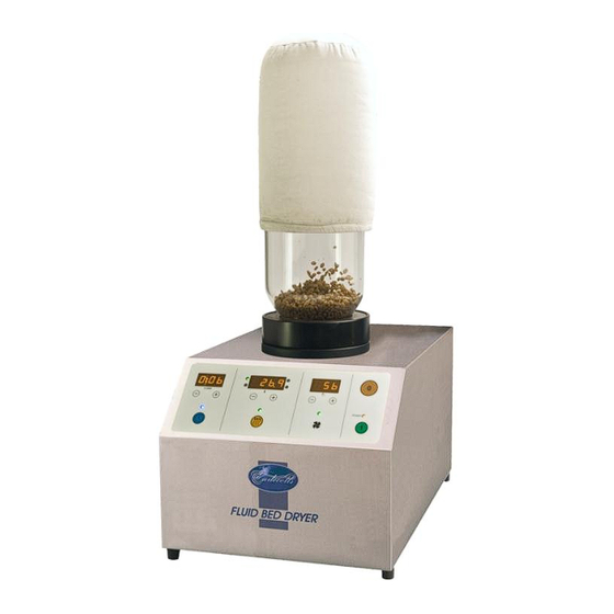
There are many types of tub assemblies to choose from which can be used with the Fluid Bed Dryer. Please contact Endecotts for details. The FBD incorporating the full range of options is illustrated below. This dryer enables the operator to have complete control a compile a record of the drying process. - Page 7 Introduction Chapter 1 (continued) Instrument Description cont/… These filters retain the sample in the tub assembly while assuring a uniform distribution of air enters the assembly. A filter top cap is clamped on to the top of the tub by means of a clamp and seals on a silicon “O” ring which also keeps the sample particles from escaping the tub assembly.
-
Page 8: Drying Tubs And Accessories
DRYING TUBS and ACCESSORIES The 5 Litre Sealed Glass Tub having a sample port and a sensor port is the standard tub assembly for the Fluid Bed Dryer. It allows full utilisation of the analytical, data capture and storage, and programming control feature on the dryer. -
Page 9: Special Notes On Accessories
Many of the main advantages of fluid bed drying may be lost. If in doubt, Endecotts offer to do an initial study on your sample which will ensure proper accessories are chosen for the application. - Page 10 The air blower is controlled by a thyristor circuit to give a smooth variation over a wide range of motor speeds, as in previous models. On the Fluid Bed Dryer, however, the blower motor speed is monitored and a feedback loop assures the blower motor speed is maintained regardless of surges in power supply or effects of a heater being switched on and off.
- Page 11 Introduction Chapter 1 (continued) Warning! When Operating a Dryer above 65°C we recommend making a copy of the following warning sign so that it can be displayed next to the instrument and tub assembly. Stick on thermal labels can be also provided for all 2 and 5 litre tub assemblies on request and should be positioned in the most visible location if the instrument will be he used at elevated temperatures.
-
Page 12: Applications
1 /3 o f t h e t u b b e i n g u s e d f o r d r y i n g . (The advantages of the fluid bed dryer can however be realised even if the sample lurches and mixing in a non-ideal manner). -
Page 13: Basic Principles Of Fluidised Beds
Introduction Chapter 1 (continued) Due to the complexities of the mixing and drying process, the optimal amount of sample to use is best determined by trial and error. The pulse flow works most effectively on “stringy” samples that will not mix, particularly when they are wet. -
Page 14: The Drying Process
Introduction Chapter 1 (continued) The Drying Process If water is added to a dry sample, it is absorbed by particles until the point at which the particles become saturated. The saturation point is known as the Critical Moisture Content. The CMC is characteristic of the sample material, and the initial water which is incorporated into the particle is held as internal moisture. - Page 15 Introduction Chapter 1 (continued) The Drying Process cont/… The process can be conducted at relatively low temperatures and there is little abrasion, since the particles are separated by air bubbles. The drying process can be analysed to show the amount of internal and external moisture. When external moisture is removed, drying can be conducted quickly, since the temperature is kept low by the evaporation of water.
- Page 16 Introduction Chapter 1 (continued) The Drying Process cont/… 5. Calculation of heat transfer coefficients for different conditions relevant to dryer design and comparison of fluidised beds with other drying methods. Other applications include: - Drying small particulates, drying particulates with a wide particle size range, drying down to a particular moisture concentration, analysis of moisture, rapid drying, homogenising samples, separating particles based on density, coating samples, etc.
-
Page 17: Operating - Overview
Operation Chapter 2 Operating: - Overview The Fluid Bed Dryer has been designed to make reproducible drying easy. The instrument should be connected to the power source and turned on from the mains switch on the back of the instrument. -
Page 18: Setting The Conditions
Operation Chapter 2 cont/… Setting the Conditions In standby mode, the variables of time, inlet temperature and blower speed can be set prior to running the instrument. There are symbols indicating the four sections. A blue clock face icon indicates the timer, the yellow radiation symbol icon indicates the heater, and a fan blade icon indicates the blower and finally the power section having on/off symbols as buttons. -
Page 19: Setting The Blower
Operation Chapter 2 cont/… Section 2 - Setting the temperature. A green flashing light above the “Heater Symbol” indicates that it is ready to receive a temperature value. The red light (SV) is illuminated in the lower left hand corner of the digital display shows that the “Set Value” of the temperature is being displayed. - Page 20 Operation Chapter 2 cont/… Section 4 - Starting and Stopping the Dryer. The dryer can be turned on, to operate according to its pre-set conditions, by pressing the green switch below the power light. Section 4 Pressing the red switch stops the dryer operation and displays the last set values.
-
Page 21: General
Operation Chapter 2 cont/… General Several conditions can be modified during a drying procedure. While operating the FBD, the timer counts down from the set time. It cannot be altered by pressing the (+) and (-) buttons. The timer function can, however, be turned off by holding down the icon button. -
Page 22: Optional Extras
Operation Chapter 2 cont/… Optional Extras There a r e t w o i n s t r u m e n t o p t i o n s , t h e f i r s t i s t h e H u m i d i t y Temperature Probe and the second is a Pulse Flow Device. -
Page 23: Installing A Pulse Flow Device
Operation Chapter 2 cont/… Operation with the H/T Probe cont/… During operation, the set value will be displayed for a few seconds and the display will automatically change back to reading the process value of temperature. The inlet and outlet temperatures as well as relative humidity will remain displayed during the operations. - Page 24 Operation Chapter 2 cont/… Operation with the Pulse Flow Device cont/… The PSD can be made to function by simply pressing the on/off switch on the device downward. The pulsing of the valve occurs in cycles of approximately 2.5 seconds closed and 2.5 seconds open. - 22-...
-
Page 25: Chapter 3 - Maintenance
Maintenance Chapter 3 WARNING! Before starting any maintenance procedure on the Fluid Bed Dryer ensure that the instrument is switched off and disconnected from the electrical supply and read all the instructions thoroughly. This is for your safety and to prevent damage to the instrument. -
Page 26: Replacement Of Flange "O" Ring
Maintenance Chapter 3 cont/… Replacement of Flange “O” Ring There is a silicon “O” ring in the flange on the top of the instrument on to w hich the tub asse mblie s seal. Should the instrument develop an air leak coming from between the tub- assembly and the instrument, this ring will have to be replaced. - Page 27 (0) on the front panel. Should the instrument behave differently than described above, please notify your dealer or call Endecotts. Failure to pass the power on tests are indicative of either an indicator or the function itself not operating correctly.
-
Page 28: Fuses
Both configurations, Type A and Type B, are shown below. Fuse Type Colour Purpose 230V 110V blue general green blower yellow heater Pulse flow View of the Back of Fluid Bed Dryer Digital Fuse type A and C are finger-turn Fuse type B and C are screwdriver - 26-... -
Page 29: Specification
Specification Model: Fluid Bed Dryer Digital Voltage: 110v or 230v Frequency: 50Hz or 60Hz Phase: Power Consumption: 3.2kW Class: E 1 (earthed) Dimensions: 260 x 340 x 495 mm (H x W x D) Weight: 19 kg - 27-... -
Page 30: General Advice
General Advice Endecotts’ shakers are fully tested and factory checked before shipping to customers. No parts require lubrication or resetting unless disturbed. The sieve shaker has been constructed and factory tested to ensure correct operation when connected to the specified electricity supply indicated on the machines rating plate. - Page 31 ZMFBD -MAN1 ISSUE 09/12 ________________________________________________________________________________________________________________ Endecotts Limited, Lombard Road, London SW19 3TZ England Tel: + 44 (0) 20 8542 8121 Fax: + 44 (0) 20 8543 6629 E-mail: sales@endecotts.com web site http://www.endecotts.com...
Need help?
Do you have a question about the Fluid Bed Dryer and is the answer not in the manual?
Questions and answers