Table of Contents
Advertisement
Advertisement
Table of Contents

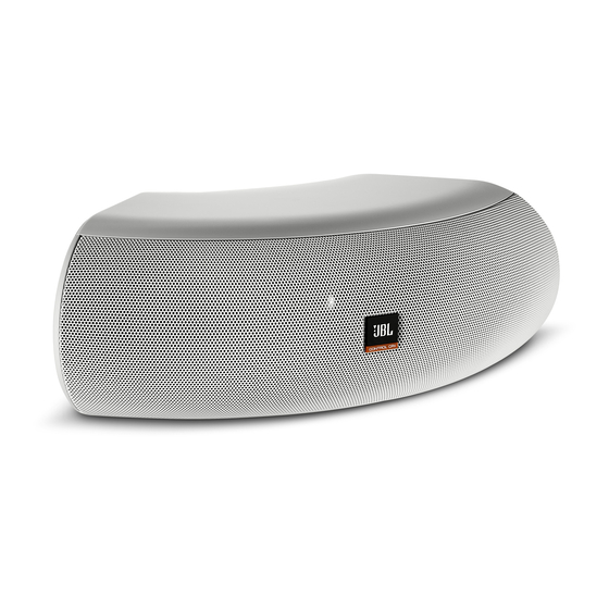
Summary of Contents for JBL Control CRV
- Page 1 JBL Control ® Owner’s Manual...
-
Page 2: Table Of Contents
TABLE OF CONTENTS JBL CONTROL® CRV LOUDSPEAKERS UNPACKING THE SPEAKERS .......2 JBL Control CRV speakers are perhaps the most fl exible and WALL SURFACE MOUNTING ......3 versatile loudspeakers ever developed. There are numerous mounting options. The JBL Control CRV speaker can be wall- WALL CORNER MOUNTING ......4... -
Page 3: Wall Surface Mounting
INSTALLATION WALL SURFACE MOUNTING bracket. Rest the JBL Control CRV speaker’s rear fl ange in the mounting bracket, as shown. This will support the weight of the speaker. Slide the mounting-bracket cap over the assembly. Secure the mounting-bracket cap by inserting two #10-32 x 2”... -
Page 4: Wall Corner Mounting
JBL Control CRV speaker into the mounting bracket. 1. Run the wiring to the location desired for mounting the JBL Control CRV speaker. 2. Attach the mounting bracket to the wall. Be sure to use appropriate anchors. - Page 5 INSTALLATION 3. Connect the stripped bare wires to the input terminals of the 6. To orient the JBL logo into the correct position, pull the JBL JBL Control CRV speaker. logo slightly outward from the speaker grille and rotate. The JBL logo is held in place by a spring.
-
Page 6: Wall Ceiling Mounting
Rest the JBL Control CRV speaker’s rear fl ange in the The installer is responsible for proper selection mounting bracket, as shown. This will support the weight of the and use of mounting hardware, to properly and speaker. -
Page 7: Half-Round Wall Mounting
INSTALLATION HALF-ROUND WALL 6. To orient the JBL logo into the correct position, pull the JBL logo slightly outward from the speaker grille and rotate. The MOUNTING JBL logo is held in place by a spring. Peel the adhesive cover... -
Page 8: 3/4 Round External Corner Wall Mounting
Run the wire through the rear cable-management hole in the mounting bracket, and rest the JBL Control CRV The installer is responsible for proper selection speaker’s rear fl ange in the mounting bracket, as shown. This and use of mounting hardware, to properly and will support the weight of the speaker. - Page 9 (side view) #10-32 x 2" Screws (2) (side view) 6. Rest the second JBL Control CRV speaker’s rear fl ange in Appropriate anchors the mounting bracket, as shown. Secure the mounting bracket cap with two #10-32 x 2” (M5 51 mm) screws through the bottom of the mounting bracket.
-
Page 10: Four Speaker Array Using
INSTALLATION FOUR-SPEAKER ARRAY 7. Rest the third JBL Control NOW speaker’s rear fl ange in the mounting bracket as shown and complete the process. Secure USING THE OPTIONAL the mounting-bracket cap with 2 screws through the bottom of POLE-MOUNT BRACKET the mounting bracket. -
Page 11: Unpacking The Bracket And Cable Kit
INSTALLATION ATTACHING POLE TO POLE-MOUNT BRACKET CAUTION: Installation must be For Larger-Diameter Drop Tubes done by qualifi ed persons using safe 1. Run the appropriate wiring down through the drop tube. Slide rigging standards the drop tube through the pole-mount-bracket cap. The installer is responsible for proper selection and use of mounting hardware, to properly and safely pole-mount the speakers. - Page 12 THRU position is not advised due to parallel speakers providing too low of an impedance for most low impedance power amplifi ers. Pole-Mount Bracket 2. Connect the stripped bare wires to the input terminals of the Clevis Pin JBL Control CRV speakers.
-
Page 13: Setting Tap Selector
Drop Tube Pole-Mount Bracket Cap SETTING TAP SELECTOR The Control CRV is designed to be driven from a 70V or 100V distributed speaker line or as a 4 ohm speaker. It is important to 1 5 W set the tap selector switch before installing the speaker. -
Page 14: Painting & Maintenance
In the USA you may call Monday through Friday 8:00am to 5:00pm Pacifi c Coast Time (800) 894-8850. Outside the USA: Contact the JBL Professional Distributor in your country. A list of JBL Professional Distributors and US Service Centers can be obtained from the JBL Professional website at: www.jblpro.com... -
Page 15: Specifications
SPECIFICATIONS SPECIFICATIONS Frequency Range (–10dB) 80Hz – 20kHz Power Handling 75 W Continuous Pink Noise, 2 hrs 60 W Continous Pink Noise, 100 hrs 150 W Continuous Program Power 300 W Continous Peak Power Nominal Sensitivity: 89 dB Maximum SPL @ 1m 108 dB continuous average long-term (peaks of 114 dB) Nominal Coverage Angle: 105°... -
Page 16: Dimensions
DIMENSIONS 364 mm (14.4 in) 262 mm (10.3 in) 251 mm (9.9 in) 127 mm (5 in) JBL Professional 8500 Balboa Boulevard, P.O. Box 2200 Northridge, CA 91329 USA OM CNTRL CRV 15M 5/09...


