Table of Contents
Advertisement
10/14
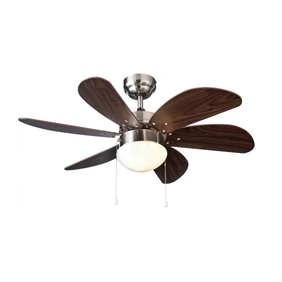
nordica 36" ceiling fan
model no. 052-2231-4
Instructions PERTAINING TO RISK OF FIRE OR
INJURY TO PERSONS. READ ALL INSTRUCTIONS
IMPORTANT SAFETY
!
INSTRUCTIONS
SAVE THESE INSTRUCTIONS
INSTALLATION AND WIRING TO BE IN
ACCORDANCE WITH CEC, NEC, LOCAL ELECTRICAL
CODES and ANSI/NFPA 70. Consult a qualified
electrician if you are not familiar with wiring.
NOTE: FOR OPTIMUM QUIETNESS, FULLY ASSEMBLE FAN AND RUN 24 HOURS
Instruction Manual
Model no.
052-2231-4
IMPORTANT: Please read and understand this manual before any assembly. Before
beginning assembly of product, make sure all parts are present. Compare parts
with packaging contents list.
Advertisement
Table of Contents

Related Manuals for Nordica 052-2231-4

Summary of Contents for Nordica 052-2231-4
- Page 1 10/14 nordica 36” ceiling fan model no. 052-2231-4 INSTRUCTIONS PERTAINING TO RISK OF FIRE OR INJURY TO PERSONS. READ ALL INSTRUCTIONS IMPORTANT SAFETY INSTRUCTIONS SAVE THESE INSTRUCTIONS INSTALLATION AND WIRING TO BE IN ACCORDANCE WITH CEC, NEC, LOCAL ELECTRICAL CODES and ANSI/NFPA 70. Consult a qualified electrician if you are not familiar with wiring.
-
Page 2: Safety Precautions
Model no. 052-2231-4 SAFETY PRECAUTIONS 1. Turn o power at main electrical service box before starting installation. 2. Electrical connections must comply with local code ordinances or national electrical codes. 3. Make sure the installation site you choose allows the fan blades to rotate freely without any obstructions. - Page 3 Model no. 052-2231-4 Rubber Bushing - 1 Ceiling Canopy - 1 Hemisphere Jam Screw & Hemisphere - 1 Lock Pin - 1 Bolt & Cotter Pin & Flat Washer - 1 Downrod c/w Ground Wire - 1 Upper Jam Screws - 2 Motor Assembly - 1 Yoke Screws &...
- Page 4 Model no. 052-2231-4 Wooden Approved (CSA for Joist Canada and UL for U.S.) ceiling fan box Ceiling (not provided) Outlet Box Screws (not provided) Without Downrod With Downrod Fig. 1...
- Page 5 Model no. 052-2231-4 Model no. 052-2231 NOTE: All set screws must be checked and retightened where necessary, before and after installation. Step 1 - DOWNROD MOUNT - Using a screwdriver, loosen the 2 upper jam screws (J) on the yoke.
- Page 6 Model no. 052-2231-4 Model no. 052-2231 WARNING: To reduce the risk of fire, electric shock, or personal injury, mount to UL/CSA listed outlet box marked acceptable for fan support and use mounting screws provided with the outlet box. Step 2 - INSTALL MOUNTING BRACKET - Install J-hook (R) through centre of outlet box and into the wooden joist.
- Page 7 Model no. 052-2231-4 Model no. 052-2231 DOWNROD MOUNT FLUSH MOUNT Ground Wire Ground Wire (Green Wire) (Green Wire) Marette Marette Fig. 4b Fig. 4a NOTE: Once ground wires are connected, carefully tuck wires and marette into the metal outlet box making sure that the wires are clear of the hemisphere and downrod when positioned in mounting bracket (Downrod Mount Only).
- Page 8 Model no. Model no. 052-2231-4 052-2231 - Carefully rotate fan assembly until groove in hemisphere locks over tab of canopy assembly. (Fig. 6b) WARNING: Failure to seat tab in groove could cause damage to electrical wires and possible shock or fire hazard.
- Page 9 Model no. Model no. 052-2231-4 052-2231 - Take out hardware containing motor screws and lock washers (L) . - Position motor screws and lock washer (L) in blade brackets (M), and secure to motor (I). Make sure all screws are tightened securely.
-
Page 10: Troubleshooting
TROUBLESHOOTING TROUBLE SUGGESTIONS 1. Fan will - Check wiring connections to fan. not start - Check fuses and circuit breakers. - Check wiring connections in switch housing. CAUTION: Turn power o for last two items. 2. Fan sounds - Check to make sure that all screws in motor housing noisy are snug.
Need help?
Do you have a question about the 052-2231-4 and is the answer not in the manual?
Questions and answers