Table of Contents
Advertisement
Advertisement
Table of Contents

Subscribe to Our Youtube Channel
Related Manuals for Extech Instruments VPC300

Summary of Contents for Extech Instruments VPC300
- Page 1 USER GUIDE Video Particle Counter with built‐in Camera Model VPC300 ...
- Page 2 The VPC300 has a Color TFT LCD display, a 74MB internal data storage bank, a micro‐SD memory card slot for capturing images and video for viewing on a PC, and a built‐in 320x240 pixel camera for capturing stills/video of test locations. The VPC300 offers quick and accurate readings for particle count, air temperature, most surface temperatures, and relative humidity. The VPC300 also offers a Dew Point and Wet Bulb temperature calculation geared for energy efficiency and ...
-
Page 3: Meter Description
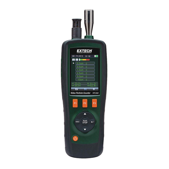
Meter Description Isokinetic probe Temperature and RH Sensor (note its protective cover that slides up and down) Color TFT LCD Compartment for USB interface port and AC Adaptor/Charger Function F1, F2, F3 buttons Control buttons: Page Up/Down, Enter, Run/Stop, and ESC ON/OFF button Battery and Micro‐SD card compartment (SD card slot underneath battery) Tripod mount 10. Camera lens 3 VPC300‐en‐GB_v1.5 5/15 ... -
Page 4: Operation
Operation Power ON‐OFF Press and hold the power button to switch the instrument ON or OFF. Important Notes Note: Operating the particle counter with the isokinetic probe cap in place will damage the pump and other internal components. Note: Electrical noise, sensor leakage, or other interference may cause the VPC300 to show incorrect particle count data. Getting Started When the meter powers ON, the Particle Counter icon is displayed at the center of the LCD and the date, time, and battery status can be observed on the top row of the LCD. Three bottom row options are also displayed and can be selected using the Function keys (F1, F2, and F3) as shown below. These are explained in greater detail later in this user guide: Memory (where data, images, and video are located) System Setup Parameters Help File Symbol Glossary Video Record start Cumulative mode Concentration mode Video mode Color coded particle scale (green is ... -
Page 5: Sequence Of Operation
3. Run your test cycles and evaluate the results. Basic Operation Press and hold the ON/OFF button for 3 to 5 seconds until the display illuminates to power on the meter. Press the enter button ( to get to setup mode. Press F3 to enter settings mode. Set each parameter to your preferred setting by pressing ENTER to enter each parameter. Then press ENTER to enable editing of each parameter. Press ESC to exit parameter setup. Sample Time: Length of time each test runs (3 to 60 seconds) Start Delay: Duration of time from RUN to actual start of test. (3 to 100 seconds) Channel Display: Particle sizes displayed during test. Ambient Temp/RH: Allows the display of the air temp and %RH values Sample Cycle: Number of test cycles to run (1 to 100) Sample Mode: Cumulative, differential, concentration Interval: Test cycle delay measured in seconds. Level Indication: Particle level selection (highlighted on display) Press ESC to return to testing screen Press RUN/STOP to start the automated test sequence. 5 VPC300‐en‐GB_v1.5 5/15 ... -
Page 6: Taking Measurements
F3 to enter the Setup mode. Use the up and down arrow keys to select an option to edit and press ENTER ( to access the selection. SAMPLE TIME (Test Cycle Time) Select Sample Time. Press the Enter ( button to enter the option and Press Enter again to activate the setting for editing. Use the arrow buttons to set the sampling time/gas volume (3 to 60 seconds). Use the Esc button to save and return to the menu. 6 VPC300‐en‐GB_v1.5 5/15 ... -
Page 7: Start Delay
Use the arrow keys to select the channel and press the Enter key to select or de‐select the channel. Use the Esc key to save the setting and to return to the menu. AMBIENT TEMPERAURE / %RH Enable or Disable the ambient temperature and relative humidity displays. From the Particle setup menu, use the Up and Down arrows to select Ambient Temp/RH. Press the Enter ( button to enter the option. Use the arrow keys to select Enable or Disable and use the ESC button to save and return to the menu. SAMPLE CYCLE Set the desired number of test cycles to run. From the Particle setup menu, use the Up and Down arrows to select Sample Cycle. Press the Enter ( button to enter the option and Press Enter again to activate the setting for editing. Use the arrow keys to select the number of cycles to run the test (1 to 100). Press ESC to save setting and to return to the menu list. 7 VPC300‐en‐GB_v1.5 5/15 ... -
Page 8: Sample Mode
INTERVAL (TIME BETWEEN REPEATED TEST CYCLES) Set the time between tests for tests with more than one cycle (1 to 100 seconds). From the Particle setup menu, use the Up and Down arrows to select Interval Time. Press the Enter ( button to enter the option and Press Enter again to activate the setting for editing. Use the arrow buttons to set the desired interval time. Use the ESC button to save setting and to return to the menu. Note: The INTERVAL setting is only for programming the time between test cycles, not between individual measurements. 8 VPC300‐en‐GB_v1.5 5/15 ... - Page 9 Select the Alarm Limit (Level) of the corresponding particle size. When the selected particle size is exceeded, the instrument alerts the user. From the Particle setup menu, use the Up and Down arrows to select Level Indication. Press the Enter ( button to enter the option. Use the arrow buttons to select the desired alarm limit and then press ESC to save setting and return to the menu. Memory Storage Browser When the meter is switched ON, these LCD icons are visible . Press F1 to enter the data memory section. There are three options available in the memory mode, Picture, Video, and Particle Logs. Use the arrow buttons to select one and then press ENTER ( to access the selection. When browsing images, data, and video use the arrow buttons to navigate, use the Enter button to select, and use the ESC or F3 button to return to the menu. Press ESC again to exit to the power‐on screen. 9 VPC300‐en‐GB_v1.5 5/15 ...
-
Page 10: System Setup Parameters
ESC button to save the setting and return to the Setup menu. LANGUAGE Select the desired language for menu text. Press the Enter ( button to open the selection for editing. Use the arrow keys to select a language and use the ESC button to save the setting and return to the Setup menu. 10 VPC300‐en‐GB_v1.5 5/15 ... -
Page 11: Auto Power Off
Enter ( button to open the selection for editing. Use the arrow keys to select the setting and use the ESC button to save the setting and return to the Setup menu. DISPLAY TIME‐OUT Select display auto‐off delay. Press the Enter ( button to open the selection for editing. Use the arrow keys to select a setting and use the ESC button to save the setting and return to the Setup menu. 11 VPC300‐en‐GB_v1.5 5/15 ... -
Page 12: Memory Status
UNITS Select the desired unit of measure for temperature C or F. Press the Enter ( button to open the selection for editing. Use the arrow keys to select the Unit and use the ESC button to save the setting and return to the Setup menu. 12 VPC300‐en‐GB_v1.5 5/15 ... - Page 13 Zero the Particle count Sensor Particles must be purged (removed) from the sensor before and after each use in a high sample count environment. Zero the sensor: Unscrew and remove the Isokinetic probe and attach the Zero count filter. Turn on the meter and in the Setup mode, Set the Sample mode to Cumulative. Set the Channel Display to ensure all channels are selected. Set Sample time to 60 seconds Set Sample Cycle to 10 Start the meter Allow the meter to run until all of the particle counts read zero. You may need to run the meter multiple times to ensure that all channels read zero. Turn off the meter. Remove the Zero count filter and attach the Isokinetic probe. 13 VPC300‐en‐GB_v1.5 5/15 ...
- Page 14 One way to determine the source of air particulates in a room is to test the air outside of the room under investigation. Determine the concentration and size of particulates at the air intake to that room. Purge or Zero the particle counter and then measure the concentration and size of particles in multiple areas of the room to be tested, to determine the effectiveness of the incoming air filtration. The air temperature, relative humidity, and CO2 levels are also an important consideration for IAQ as high humidity and lower temperatures can bring about mold creation. If a room is classified as an ISO clean room or clean zone, the counts of particle sizes for that class cannot be exceeded when tested. Refer to the ISO Clean Room Class chart (ISO 14644‐1:1999) for values. The VPC300 is equipped with a still/video camera to directly see the areas under test. Data, images, and video can be stored on up to an 8GB micro‐SD card (not included) or in the meter’s internal 74MB memory. The life of the meter can be maximized by testing only when necessary and securely storing the instrument when it is not in use. Continuous use is not recommended and can shorten the life of the instrument especially in dusty environments. Setting up a common sense maintenance schedule and testing to the schedule will go a long way in lengthening the life of the instrument sensor. PC Interface and Supplied PC software This meter has the capability to connect to and communicate with a PC. A USB cable is supplied and connects to the jack on the meter’s left side compartment. To install and use the software, please refer to the instructions provided on the supplied CD‐...
-
Page 15: Battery Charging And Replacement
Battery Charging and Replacement When the battery icon appears drained on the LCD or if the meter will not switch ON, the battery must be recharged using the supplied AC adaptor/charger. The charger plug connects to the jack located on the meter’s left side compartment. The battery compartment is located on the rear of the instrument. The battery is a 7.4V Lithium‐ion polymer rechargeable battery. To access the meter’s battery for replacement: On the rear of the meter, remove the Phillips head screw that secures the battery compartment. Open the compartment by carefully lifting the compartment cover. Replace the battery with one of the same type (note that the Micro‐SD card slot is located underneath the battery as explained below). Close the compartment and secure the compartment cover with the Phillips head screw Battery Safety Reminders Please dispose of batteries responsibly; observe local, state, and national regulations. Never dispose of batteries in fire; batteries may explode or leak. Always install a new battery of the same type. Micro‐SD Card Slot (optional) The micro‐SD card slot is located inside the battery compartment underneath the battery. Micro‐SD cards up to 8GB can be inserted in the slot. To access the SD memory card slot: Turn off power to the meter and remove the AC adapter cable if connected. Open the battery compartment as described in the battery replacement section. Remove the battery. Insert a micro‐SD card (8GB max.) in the card slot underneath the battery by lifting up on the metal card holder and placing the Micro SD card in the connector. The pins facing towards the top of the meter. Close the metal holder. Insert the battery and secure the compartment cover before powering on the meter. 15 VPC300‐en‐GB_v1.5 5/15 ... -
Page 16: General Specifications
Accommodates up an 8GB card Meter internal memory 5000 sample records; 74MB Power supply Rechargeable 7.4V Lithium‐ion polymer battery Battery life Approx. 4 hours of continuous use Battery charge time 2 hours approx. with AC adaptor/charger Operating Temperature 32 to 122 F (0 to 50 C) Operating/Storage Humidity 10 to 90% RH non‐condensing Storage Temperature 14 to 140 F (‐10 to 60 C) Dimensions 9.4 x 3.0 x 2.2” (240 x 75 x 57mm) Weight 1.26 lbs. (570g) Copyright © 2014‐2015 FLIR Systems, Inc. All rights reserved including the right of reproduction in whole or in part in any form ISO‐9001 Certified www.extech.com 16 VPC300‐en‐GB_v1.5 5/15 ...
Need help?
Do you have a question about the VPC300 and is the answer not in the manual?
Questions and answers