Table of Contents
Advertisement
SERVICE MANUAL
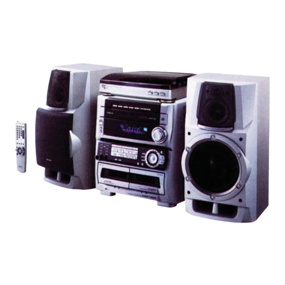
COMPACT DISC STEREO
CASSETTE RECEIVER
SYSTEM
Z–HT730
• This Service Manual is the "Revision Publishing" and replaces "Simple Manual"
Z-HT730, (S/M Code No. 09-003-422-7T3).
• If requiring information about the CD mechanism, see Service Manual of
6ZG-1, (S/M Code No. 09-001-338-7N2).
Z-HT730
BASIC TAPE MECHANISM : 2ZM-3MK2 PR5NM
BASIC CD MECHANISM : 6ZG-1 ZRDM
CD
SPEAKER
CASSEIVER
SX–ZHT730
CX–ZHT730
SX–CR677
S/M Code No. 09-006-433-9R1
K, EZ
REMOTE
CONTROLLER
RC–ZAS05
Advertisement
Table of Contents

Related Manuals for Aiwa Z-HT730


Summary of Contents for Aiwa Z-HT730
- Page 1 RC–ZAS05 SX–CR677 • This Service Manual is the "Revision Publishing" and replaces "Simple Manual" Z-HT730, (S/M Code No. 09-003-422-7T3). • If requiring information about the CD mechanism, see Service Manual of 6ZG-1, (S/M Code No. 09-001-338-7N2). S/M Code No. 09-006-433-9R1...
-
Page 2: Specifications
SPECIFICATIONS FM tuner section Cassette deck section Tuning range 87.5 MHz to 108 MHz Track format 4 tracks, 2 channels stereo Usable sensitivity (IHF) 13.2 dBf Frequency response : tape: 50 Hz - 16000 Hz Antenna terminals 75 ohms (unbalanced) Normal tape: 50 Hz - 15000 Hz Signal-to-noise ratio 50 dB (CrO... -
Page 3: Protection Of Eyes From Laser Beam During Servicing
PROTECTION OF EYES FROM LASER BEAM DURING SERVICING This set employs laser. Therefore, be sure to follow carefully CAUTION the instructions below when servicing. Use of controls or adjustments or performance of proce- dures other than those specified herin may result in WARNING!! hazardous radiation exposure. -
Page 4: Note On Before Starting Repair
NOTE ON BEFORE STARTING REPAIR 1. Forced discharge of electrolytic capacitor of power supply block When repair is going to be attempted in the set that uses relay circuit in the power supply block, electric potential is kept charged across the electrolytic capacitors (C101, 102) even though AC power cord is removed. - Page 5 In such a case, check also if the POWER AMPLIFIER circuit or power supply circuit has any abnormalities or not. 2-2. Regarding reset There are cases that the machine does not work correctly because the MICROCOMPUTER is not reset even though the AC power cord is re-inserted, or the software reset (pressing the STOP key + POWER key) is performed.
-
Page 6: Electrical Main Parts List
ELECTRICAL MAIN PARTS LIST REF. NO. PART NO. KANRI DESCRIPTION REF. NO. PART NO. KANRI DESCRIPTION 87-A40-751-080 ZENER,UZ6.2BSB 87-A40-760-080 ZENER,UZ9.1BSA 87-A21-397-010 IC,STK490-070 87-A40-747-080 ZENER,UZ5.1BSB 87-A21-021-040 C-IC,BU2099FV 87-A40-438-080 ZENER,MTZJ4.7A 87-A20-783-040 C-IC,BA7762AFS 87-017-149-080 ZENER,HZS6A2L 87-A21-577-040 C-IC,M61506FP 87-A21-097-040 C-IC,M62463AFP MAIN C.B 87-A21-482-010 IC,RPM6938-H4 87-A21-015-040 C-IC,M62491FP 87-A10-712-080... - Page 7 REF. NO. PART NO. KANRI DESCRIPTION REF. NO. PART NO. KANRI DESCRIPTION C355 87-010-178-080 CHIP CAP 1000P C456 87-A10-801-080 C-CAP,S 0.022-16 J B CM C356 87-010-260-080 CAP, ELECT 47-25V C457 87-016-081-080 C-CAP,S 0.1-16 RK C357 87-010-197-080 CAP, CHIP 0.01 DM C461 87-010-196-080 CHIP CAPACITOR,0.1-25...
- Page 8 REF. NO. PART NO. KANRI DESCRIPTION REF. NO. PART NO. KANRI DESCRIPTION C790 87-A10-801-080 C-CAP,S 0.022-16 J B CM C984 87-010-197-080 CAP, CHIP 0.01 DM C791 87-010-196-080 CHIP CAPACITOR,0.1-25 C985 87-010-322-080 C-CAP,S 100P-50 CH C792 87-010-197-080 CAP, CHIP 0.01 DM C987 87-010-197-080 CAP, CHIP 0.01 DM...
- Page 9 REF. NO. PART NO. KANRI DESCRIPTION REF. NO. PART NO. KANRI DESCRIPTION SFR351 87-A90-433-080 SFR,50K H NVZ6TLTA FC102 88-914-231-110 FF-CABLE,14P 1.25 SFR352 87-A90-433-080 SFR,50K H NVZ6TLTA FC103 88-920-151-110 FF-CABLE,20P 1.25 TC942 87-011-253-080 TRIMER,30P LAR FC104 88-915-151-110 FF-CABLE,15P 1.25 150MM 87-A90-510-010 HLDR,WIRE 2.5-9P FL101 8A-MA3-651-010...
- Page 10 REF. NO. PART NO. KANRI DESCRIPTION REF. NO. PART NO. KANRI DESCRIPTION S808 87-A90-095-080 SW,TACT EVQ11G04M R166 87-A00-418-010 RES,M/F 0.15-3W J S809 87-A90-095-080 SW,TACT EVQ11G04M TH101 87-A91-042-080 C-THMS,100K 55001 S810 87-A90-095-080 SW,TACT EVQ11G04M TH102 87-A91-042-080 C-THMS,100K 55001 S811 87-A90-095-080 SW,TACT EVQ11G04M WH102 87-A90-460-010 HLDR WIRE 2.5-7P...
-
Page 11: Chip Resistor Part Code
REF. NO. PART NO. KANRI DESCRIPTION REF. NO. PART NO. KANRI DESCRIPTION LED775 87-A40-317-080 LED,SLR-342VCT31 RED C107 87-A11-148-080 CAP,TC U 0.1-50 Z F S751 87-A90-095-080 SW,TACT EVQ11G04M C108 87-A11-148-080 CAP,TC U 0.1-50 Z F S752 87-A90-095-080 SW,TACT EVQ11G04M C109 87-A11-148-080 CAP,TC U 0.1-50 Z F S753 87-A90-095-080... -
Page 12: Transistor Illustration
TRANSISTOR ILLUSTRATION E C B E C B E C B B C E KTA1266GR CC5551 CSC4115BC 2SB1370 KTC3198GR 2SD1933 CD1585BC 2SB1342 CSA952K FN1016 FP1016 E C B G D S E C B 2SK2158 DTC114ES 2SK3053 2SB1237Q KTC3199GR 2SA933SRS 2SA1235F CSD1306E 2SK360E... - Page 13 WIRING - 1 (MAIN / VM) – 13 –...
- Page 14 SCHEMATIC DIAGRAM - 1 (MAIN 1/4 : AMP / VM) – 14 –...
- Page 15 SCHEMATIC DIAGRAM - 2 (MAIN 2/4 : DECK / HEAD-1 / HEAD-2) – 15 –...
- Page 16 SCHEMATIC DIAGRAM - 3 (MAIN 3/4 : TUNER) – 16 –...
- Page 17 SCHEMATIC DIAGRAM - 4 (MAIN 4/4 : PRO) – 17 –...
- Page 18 WIRING - 2 (MICON) – 18 –...
- Page 19 SCHEMATIC DIAGRAM - 5 (MICON / DECK) – 19 –...
- Page 20 WIRING - 3 (CNTL) – 20 –...
- Page 21 SCHEMATIC DIAGRAM - 6 (CNTL / KEY CD / DK1 LED / DK2 LED / MIC) – 21 –...
- Page 22 WIRING - 4 (KEY CD / DK1 LED / DK2 LED / MIC) – 22 –...
- Page 23 WIRING - 5 (AMP 1F) – 23 –...
- Page 24 SCHEMATIC DIAGRAM - 7 (AMP 1F) – 24 –...
- Page 25 WIRING - 6 (AMP 2F) – 25 –...
- Page 26 SCHEMATIC DIAGRAM - 8 (AMP 2F) – 26 –...
- Page 27 WIRING - 7 (PT) – 27 –...
- Page 28 SCHEMATIC DIAGRAM - 9 (PT) – 28 –...
- Page 29 WIRING - 8 (DECK / HEAD-1 / HEAD-2) – 29 –...
-
Page 30: Ic Block Diagram
IC BLOCK DIAGRAM IC, BU2099FV IC, M61506FP IC, LC72131D IC, LA1843 – 30 –... - Page 31 IC, M62463AFP IC, BA7762AFS IC, BU1920FS IC, BD3876KS2 – 31 –...
- Page 32 IC, M62491FP IC, BU2092F – 32 –...
- Page 33 ADJUSTMENT <TUNER / DECK / MICON> MAIN C.B TC942 L802 L801 TP4 (DC BALANCE) IC801 L941 TP3 (DC BALANCE) SFR352 SFR351 L951 TP2 (CLK) L942 (3/3) (1/3) TP1 (VT) FFE831 TP5 (LCH) TP6 (RCH) MICON C.B FL101 IC101 L101 (O-KSCAN) TP8(GND) TP8 (D-GND) DECK C.B...
- Page 34 < TUNER SECTION > 1. Clock Frequency Check 7. FM VT Check Settings : • Test point : TP2 (CLK) Settings : • Test point : TP1 (VT) Method : Set to MW 1602kHz and check that the test point is Method : Set to FM 108.0MHz and check that the test 2052kHz ±...
- Page 35 < DECK SECTION > 16. REC/PB Frequency Response Adjustment (DECK 2) 12. Tape Speed Adjustment (DECK 2) Settings : • Test tape : TTA–602 Settings : • Test tape : TTA–100 • Test point : TP5(Lch), TP6(Rch) • Test point : TP5(Lch), TP6(Rch) •...
- Page 36 IC DESCRIPTION IC, LC876580W-5P55 Pin No. Pin Name Description M-CLK Common serial clock. M-DATA Common serial data. M-STB Common serial strobe. PLL-CE Tuner PLL IC chip enable. SR-LCK Shift register IC LATCH clock. RYM-CS RHYTHM IC chip select. POWER Audio power ON/OFF. MUTE System MUTE ON/OFF.
- Page 37 Pin No. Pin Name Description P27/RHYTHM FL segment P27 output / RHYTHM function detection. "H" : ON (Not used) P26/KEYCON FL segment P26 output / KEYCON function detection. "H" : ON P25/5MODE FL segment P25 output / GEQ 5MODE select. "H" : 5 MODE (Not used) P24/ECO FL segment P24 output / ECO mode detection.
- Page 38 FL (BJ751GNK) GRID ASSIGNMENT AND ANODE CONNECTION GRID ASSIGNMENT – 38 –...
- Page 39 ANODE CONNECTION – 39 –...
-
Page 40: Mechanical Exploded View
MECHANICAL EXPLODED VIEW 1 / 1 – 40 –... -
Page 41: Mechanical Parts List
20 8A-MA3-034-010 PANEL,CD LED 64 87-MA3-062-010 FOOT, H17 21 8A-MA3-037-010 PANEL ASSY,TRAY 3 65 8A-MA3-045-010 PANEL,SIDE L 3 22 87-B00-002-010 BADGE,AIWA 30 ABS SIL 66 8A-MA3-046-010 PANEL,SIDE R 3 23 87-NF4-216-010 HLDR,LOCK 1 67 8A-MAP-110-010 PLATE,DPL 24 8A-MA3-093-010 KNOB ASSY,RTRY JOG... -
Page 42: Tape Mechanism Exploded View
TAPE MECHANISM EXPLODED VIEW 1 / 1 PH(DECK 1) RPH(DECK 2) DECK C.B SOL 2 SOL 1 (DECK 2) (DECK 1) HEAD 1 C.B(DECK 1) HEAD 2 C.B(DECK 2) (DECK 1) (DECK 1) (DECK 2) (DECK 2) – 42 –... -
Page 43: Tape Mechanism Parts List
TAPE MECHANISM PARTS LIST 1 / 1 REF. NO. PART NO. KANRI DESCRIPTION REF. NO. PART NO. KANRI DESCRIPTION 1 82-ZM3-301-519 CHAS ASSY,M2 36 82-ZM1-236-019 CAPSTAN N 2-41.5 2 82-ZM1-258-110 SPR-T,PINCH L 37 82-ZM1-239-019 CAPSTAN N 2.2-41.7 3 82-ZM1-341-110 LVR ASSY,PINCH L2 38 82-ZM1-322-019 SPR-T,FR60 4 82-ZM1-333-010... - Page 44 SPEAKER DISASSEMBLY INSTRUCTIONS Type.1 Type.4 Insert a flat-bladed screwdriver into the position indicated by the TOOLS arrows and remove the panel. Remove the screws of each speaker 1 Plastic head hammer unit and then remove the speaker units. 2 (() flat head screwdriver 3 Cut chisel How to Remove the PANEL, FR Type.2...
-
Page 45: Accessories / Package List
PANEL,FR 2 8A-MSF-002-010 RING,W 3 8A-MSF-003-010 PLATE,NAME 4 8A-MSF-004-010 PROTECTOR,TW 5 8A-MSF-005-010 GRILLE,FRAME ASSY 6 8A-NSJ-006-010 BADGE,AIWA S35 7 8A-MSD-601-010 SPKR,W 200 8 8A-MS2-605-110 SPKR,TW 60 9 88-NSK-610-010 SPKR,CERAMIC ASSY 10 87-NS7-611-010 CORD,SPKR SPEAKER PARTS LIST (SX-CR677 YSTC) NOTE: This SX-CR677 speaker contains SX-C607 (center speaker) and SX-R277 (rear speaker). - Page 46 2–11, IKENOHATA 1–CHOME, TAITO-KU, TOKYO 110, JAPAN TEL:03 (3827) 3111 9301978 9630472 0251431 Printed in Singapore...