Table of Contents
Advertisement
Advertisement
Table of Contents

Summary of Contents for Super Micro General X11SSM
- Page 1 X11SSM(-F) X11SSL(-F) USER MANUAL Revision 1.0b...
- Page 2 The information in this User Manual has been carefully reviewed and is believed to be accurate. The vendor assumes no responsibility for any inaccuracies that may be contained in this document, and makes no commitment to update or to keep current the information in this manual, or to notify any person or organization of the updates. Please Note: For the most up-to-date version of this manual, please see our website at www.supermicro.com.
-
Page 3: About This Manual
For processor/memory updates, please refer to our website at http://www. supermicro.com/products/. * The X11SSM(-F) supports the Intel C236 chip, and the X11SSL(-F), the C232 chip. ** Intel Node Manager is supported by the X11SSM-F only. Conventions Used in the Manual... -
Page 4: Contacting Supermicro
X11SSM(-F)/X11SSL(-F) User Manual Contacting Supermicro Headquarters Address: Super Micro Computer, Inc. 980 Rock Ave. San Jose, CA 95131 U.S.A. Tel: +1 (408) 503-8000 Fax: +1 (408) 503-8008 Email: marketing@supermicro.com (General Information) support@supermicro.com (Technical Support) Website: www.supermicro.com Europe Address: Super Micro Computer B.V. -
Page 5: Table Of Contents
Preface Table of Contents Chapter 1 Introduction 1.1 Checklist ..........................7 Quick Reference .......................11 Quick Reference Table ......................12 Motherboard Features .......................14 1.2 Processor and Chipset Overview ..................18 1.3 Special Features ........................18 1.4 System Health Monitoring ....................19 1.5 ACPI Features ........................19 1.6 Power Supply ........................20 1.7 Serial Port ...........................20 Chapter 2 Installation 2.1 Static-Sensitive Devices .....................21... - Page 6 X11SSM(-F)/X11SSL(-F) User Manual 2.6 Front Control Panel ......................40 2.7 Connectors .........................45 Power Connections ......................45 Headers ..........................47 2.8 Jumper Settings .........................56 How Jumpers Work ......................56 2.9 LED Indicators ........................61 Chapter 3 Troubleshooting 3.1 Troubleshooting Procedures ....................64 3.2 Technical Support Procedures ...................68 3.3 Frequently Asked Questions ....................69...
-
Page 7: Chapter 1 Introduction
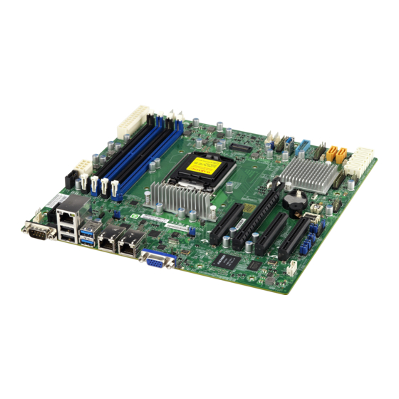
Several important parts that are included with the motherboard are listed below. If anything listed is damaged or missing, please contact your retailer. 1.1 Checklist Main Parts List Description Part Number Quantity Supermicro Motherboard X11SSM(-F)/X11SSL(-F) 1 SATA Cables CBL-0044L I/O Shield MCP-260-00042-0N Quick Reference Guide MNL-1785-QRG Important Links For your system to work properly, please follow the links below to download all necessary drivers/utilities and the user’s manual for your server. - Page 8 X11SSM(-F)/X11SSL(-F) User Manual Figure 1-1. X11SSM(-F) Motherboard Image Note: All graphics shown in this manual were based upon the latest PCB revision available at the time of publication of the manual. The motherboard you received may or may not look exactly the same as the graphics shown in this manual.
- Page 9 Chapter 1: Introduction Figure 1-2. X11SSL(-F) Motherboard Image...
- Page 10 X11SSM(-F)/X11SSL(-F) User Manual Figure 1-3. X11SSM(-F)/X11SSL(-F) Motherboard Layout (not drawn to scale) LAN2 LAN1 USB6/7 USB0/1 (3.0) JUIDB1 COM1 IPMI_LAN LED BMC JPL2 JPL1 MAC CODE X11SSM(-F)/X11SSL(-F) REV:1.01 Designed in the USA USB2/3 JBT1 Intel PCH I-SATA7 USB10(3.0) LED PWR...
-
Page 11: Quick Reference
COM1 JOH1 FAN4 LEDBMC IPMI_LAN JIPMB1 LED BMC COM2 JPL2 JPL1 JPG1 JPL2 JPL1 JBR1 MAC CODE JPME2 JPB1 X11SSM(-F)/X11SSL(-F) REV:1.01 JI2C1 JI2C2 Designed in the USA JPI2C1 JPWR2 USB2/3 USB2/3 JBT1 JBT1 JTPM1 Intel PCH JWD1 USB4/5 JSTBY1 JSD1... -
Page 12: Quick Reference Table
COM2 Port Header [X11SSM(-F) only] Fan1-Fan4, FanA System/CPU Fan Headers IPMI LAN Dedicated IPMI Gigabit (RJ45) Port (X11SSM-F & X11SSL-F only) I-SATA0-I-SATA5 (Intel PCH) Serial ATA (SATA) 3.0 Ports I-SATA6 & I-SATA7 (Intel PCH) Serial ATA (SATA) 3.0 Ports [X11SSM(-F) only]... - Page 13 Connector Description PCI-E (PCH) Slot 5 PCI-Express 3.0 x4in x8 Slot PCI-E (PCH) Slot 4 PCI-Express 3.0 x4in x8 Slot [X11SSM(-F) only] Internal Speaker/Buzzer USB 0/1 Back Panel USB 2.0 Ports USB 2/3, USB 4/5 Front Accessible USB 2.0 Headers USB 6/7 Back Panel USB 3.0 Ports...
-
Page 14: Motherboard Features
• Intel® C232 PCH (X11SSL/-F) Expansion Slots • Two (2) PCI Express 3.0 x4in x8 slots (PCH slots 4 & 5) [slot 4 on X11SSM(-F) only] • One (1) PCI Express 3.0 x8in x16 slot (CPU slot 6) • One (1) PCI Express 3.0 x8 slot (CPU slot 7) Network •... - Page 15 Low noise fan speed control System Management • Trusted Platform Module (TPM) support • PECI (Platform Environment Control Interface) 2.0 support • Node Manager Support (X11SSM-F only) • IPMI View • System resource alert via SuperDoctor® 5 • SuperDoctor® 5, Watch Dog, NMI •...
- Page 16 X11SSM(-F)/X11SSL(-F) User Manual Motherboard Features LED Indicators • CPU/Overheating • Fan Failure • UID/remote UID • LAN activity • HDD activity Other • RoHS 6/6 (Full Compliance, Lead Free) Dimensions • Micro ATX form factor (9.6" x 9.6") (243.84 mm x 243.84 mm) Note 1: The CPU maximum thermal design power (TDP) is subject to chassis and heatsink cooling restrictions.
-
Page 17: System Block Diagram
Chapter 1: Introduction Figure 1-4. System Block Diagram #A-2 #A-1 IMVP 8 3 PHASE for Vcore #B-2 #B-1 PCI-E X8 Gen3 PCIe3.0 x8 (in x8) #8-15 Skt-H4 PCI-E X8 Gen3 LGA1151 #0-7 PCIe3.0 x8 (in x16) DMI3 DMI3 x4 PCI-E x4 Gen3 PCI-E X1 Gen3 LAN1 PCIe3.0 x4 (in x8) -
Page 18: Processor And Chipset Overview
Intel Rapid Storage Technology • Intel Virtualization Technology for Directed I/O (Intel VT-d) Note: The Intel C236 PCH is supported by the X11SSM(-F) series. The C232 PCH is supported by the X11SSL(-F) series. 1.3 Special Features This section describes the health monitoring features of the X11SSM(-F)/X11SSL(-F) motherboard. -
Page 19: System Health Monitoring
Chapter 1: Introduction 1.4 System Health Monitoring The motherboard has an onboard Baseboard Management Controller (BMC) chip that supports system health monitoring. Onboard Voltage Monitors The onboard voltage monitor will continuously scan crucial voltage levels. Once a voltage becomes unstable, it will give a warning or send an error message to the screen. Users can adjust the voltage thresholds to define the sensitivity of the voltage monitor. -
Page 20: Power Supply
1.7 Serial Port The X11SSM(-F) motherboard supports two serial communication connections. X11SSL(-F) supports COM Port 1 only. COM Ports 1 and 2 can be used for input/output. The UART provides legacy speeds with a baud rate of up to 115.2 Kbps as well as an advanced speed with baud rates of 250 K, 500 K, or 1 Mb/s, which support high-speed serial communication devices. -
Page 21: Chapter 2 Installation
Chapter 2: Installation Chapter 2 Installation 2.1 Static-Sensitive Devices Electrostatic Discharge (ESD) can damage electronic com ponents. To prevent damage to your motherboard, it is important to handle it very carefully. The following measures are generally sufficient to protect your equipment from ESD. Precautions •... -
Page 22: Motherboard Installation
X11SSM(-F)/X11SSL(-F) User Manual 2.2 Motherboard Installation All motherboards have standard mounting holes to fit different types of chassis. Make sure that the locations of all the mounting holes for both the motherboard and the chassis match. Although a chassis may have both plastic and metal mounting fasteners, metal ones are highly recommended because they ground the motherboard to the chassis. -
Page 23: Installing The Motherboard
Chapter 2: Installation Installing the Motherboard 1. Install the I/O shield into the back of the chassis. 2. Locate the mounting holes on the motherboard. See the previous page for the location. 3. Locate the matching mounting holes on the chassis. Align the mounting holes on the motherboard against the mounting holes on the chassis. -
Page 24: Processor And Heatsink Installation
X11SSM(-F)/X11SSL(-F) User Manual 2.3 Processor and Heatsink Installation Warning: When handling the processor package, avoid placing direct pressure on the label area of the fan. Important: • Always connect the power cord last, and always remove it before adding, removing or changing any hardware components. - Page 25 Chapter 2: Installation 2. Gently lift the load lever to open the load plate. Remove the plastic cap. 3. Use your thumb and your index finger to hold the CPU at the North center edge and the South center edge of the CPU. North Center Edge South Center Edge 4.
- Page 26 X11SSM(-F)/X11SSL(-F) User Manual 5. Do not rub the CPU against the surface or against any pins of the socket to avoid damaging the CPU or the socket. 6. With the CPU inside the socket, inspect the four corners of the CPU to make sure that the CPU is properly installed.
-
Page 27: Installing An Active Cpu Heatsink With Fan
Chapter 2: Installation Installing an Active CPU Heatsink with Fan 1. Locate the CPU fan power connector on the motherboard. (Refer to the layout on Thermal Grease the right for the CPU fan location.) 2. Position the heatsink so that the heatsink fan wires are closest to the CPU fan power connector and are not interfering with other components. - Page 28 X11SSM(-F)/X11SSL(-F) User Manual 7. Align the four heatsink fasteners with the mounting holes on the motherboard. Gently push the pairs of diagonal fasteners (#1 & #2, and #3 & #4) into the mounting holes until you hear a click. Also, make sure to orient each fastener so that the narrow end of the groove is pointing outward.
-
Page 29: Removing The Active Heatsink
Chapter 2: Installation Removing the Active Heatsink Note: We do not recommend that the CPU or the heatsink be removed. However, if you do need to remove the heatsink, please follow the instructions below to remove the heatsink and to prevent damage done to the CPU or other components. -
Page 30: Installing A Passive Cpu Heatsink
X11SSM(-F)/X11SSL(-F) User Manual Installing a Passive CPU Heatsink 1. Do not apply thermal grease to the heatsink or the CPU die; the required amount has already been applied. 2. Place the heatsink on top of the CPU so that the four mounting holes are aligned with those on the motherboard and the underlying heatsink bracket. -
Page 31: Removing The Passive Heatsink
Chapter 2: Installation Removing the Passive Heatsink Note: We do not recommend that the CPU or the heatsink be removed. However, if you do need to remove the heatsink, please follow the instructions below to remove the heatsink and to prevent damage done to the CPU or other components. 1. -
Page 32: Memory Support And Installation
Memory Support The X11SSM(-F)/X11SSL(-F) motherboard supports up to 64GB of unbuffered (UDIMM) DDR4 ECC 2133/1866/1600/1333MHz memory in four memory slots. Populating these DIMM slots with memory modules of the same type and size will result in interleaved memory, which will improve memory performance. -
Page 33: Dimm Module Population Sequence
DIMMB2 (Blue Slot) Towards the edge of the motherboard LAN2 LAN1 USB6/7 USB0/1 (3.0) JUIDB1 COM1 IPMI_LAN LED BMC JPL2 JPL1 MAC CODE X11SSM(-F)/X11SSL(-F) REV:1.01 Designed in the USA USB2/3 JBT1 Intel PCH I-SATA7 USB10(3.0) LED PWR FAN2 FAN1 I-SATA2 DIMMB2 FANA... -
Page 34: Dimm Installation
X11SSM(-F)/X11SSL(-F) User Manual DIMM Installation LAN2 LAN1 USB6/7 USB0/1 (3.0) JUIDB1 COM1 1. Insert the desired number of DIMMs into IPMI_LAN LED BMC the memory slots, starting with DIMMB2 JPL2 JPL1 MAC CODE (Channel B, Slot 2, blue slot). For best X11SSM(-F)/X11SSL(-F) REV:1.01... -
Page 35: Rear I/O Ports
See Figure 2-2 below for the locations and descriptions of the various I/O ports on the rear of the motherboard. LAN2 LAN1 USB6/7 USB0/1 (3.0) JUIDB1 COM1 IPMI_LAN LED BMC JPL2 JPL1 MAC CODE X11SSM(-F)/X11SSL(-F) REV:1.01 Designed in the USA USB2/3 JBT1 Intel PCH I-SATA7 USB10(3.0) LED PWR FAN2 FAN1 I-SATA2 FANA FAN3 Figure 2-2. - Page 36 Serial Ports One COM connection (COM1) is located on X11SSM(-F)/X11SSL(-F), on the I/O back panel. X11SSM(-F) has an additional COM connection (COM2) located next to COM1. See the table below for pin definitions. COM Port Pin Definitions...
-
Page 37: Lan Ports
LAN1 USB6/7 USB0/1 (3.0) JUIDB1 COM1 2. LAN2 IPMI_LAN LED BMC 3. IPMI LAN (-F JPL2 JPL1 versions only) MAC CODE X11SSM(-F)/X11SSL(-F) REV:1.01 Designed in the USA USB2/3 JBT1 Intel PCH I-SATA7 USB10(3.0) LED PWR FAN2 FAN1 I-SATA2 FANA FAN3... - Page 38 X11SSM(-F)/X11SSL(-F) User Manual Universal Serial Bus (USB) Ports There are two USB 2.0 ports (USB0/1) and two USB 3.0 ports (USB6/7) located on the I/O back panel. The motherboard also has two front access USB 2.0 headers (USB2/3 and USB4/5) and one front access USB 3.0 header (USB8/9). The USB10 header is USB 3.0 Type A.
- Page 39 1. USB0/1 USB6/7 USB0/1 JUIDB1 (3.0) COM1 2. USB2/3 IPMI_LAN LED BMC 3. USB4/5 JPL2 JPL1 4. USB6/7 MAC CODE X11SSM(-F)/X11SSL(-F) 5. USB8/9 REV:1.01 Designed in the USA 6. USB10 USB2/3 JBT1 Intel PCH I-SATA7 USB10(3.0) LED PWR FAN2 FAN1 I-SATA2...
-
Page 40: Front Control Panel
X11SSM(-F)/X11SSL(-F) User Manual 2.6 Front Control Panel JF1 contains header pins for various buttons and indicators that are normally located on a control panel at the front of the chassis. These connectors are designed specifically for use with Supermicro chassis. See the figure below for the descriptions of the front control panel buttons and LED indicators. -
Page 41: Power Button
Chapter 2: Installation Power Button The Power Button connection is located on pins 1 and 2 of JF1. Momentarily contacting both pins will power on/off the system. This button can also be configured to function as a suspend button (with a setting in the BIOS - see Chapter 4). To turn off the power when the system is in suspend mode, press the button for 4 seconds or longer. - Page 42 X11SSM(-F)/X11SSL(-F) User Manual Power Fail LED The Power Fail LED connection is located on pins 5 and 6 of JF1. Refer to the table below for pin definitions. Power Fail LED Pin Definitions (JF1) Pin# Definition 3.3V PWR Supply Fail...
- Page 43 Chapter 2: Installation NIC1/NIC2 (LAN1/LAN2) The NIC (Network Interface Controller) LED connection for LAN port 1 is located on pins 11 and 12 of JF1, and the LED connection for LAN port 2 is on pins 9 and 10. Attach the NIC LED cables here to display network activity.
-
Page 44: Nmi Button
X11SSM(-F)/X11SSL(-F) User Manual Power LED The Power LED connection is located on pins 15 and 16 of JF1. Refer to the table below for pin definitions. Power LED Pin Definitions (JF1) Pin# Definition 3.3V PWR LED NMI Button The non-maskable interrupt button header is located on pins 19 and 20 of JF1. Refer to the table below for pin definitions. -
Page 45: Connectors
Required Connection LAN2 LAN1 1. 24-Pin ATX Main PWR USB6/7 USB0/1 JUIDB1 (3.0) COM1 IPMI_LAN LED BMC JPL2 JPL1 MAC CODE X11SSM(-F)/X11SSL(-F) REV:1.01 Designed in the USA USB2/3 JBT1 Intel PCH I-SATA7 USB10(3.0) LED PWR FAN2 FAN1 I-SATA2 FANA FAN3... - Page 46 X11SSM(-F)/X11SSL(-F) User Manual Secondary Power Connector JPWR2 must also be connected to the power supply. This connector is used to power the processor(s). +12V 8-pin Power Pin Definitions Pin# Definition 1 - 4 Ground 5 - 8 +12V Required Connection Important: To provide adequate power supply to the motherboard, be sure to connect the 24-pin ATX PWR and the 8-pin PWR connectors to the power supply.
-
Page 47: Headers
Headers Fan Headers The X11SSM(-F)/X11SSL(-F) has five fan headers (Fan1-Fan4, FanA). All of these 4-pin fan headers are backwards-compatible with the traditional 3-pin fans. However, fan speed control is available for 4-pin fans only by Thermal Management via the IPMI 2.0 interface. Refer to the table below for pin definitions. -
Page 48: Chassis Intrusion
X11SSM(-F)/X11SSL(-F) User Manual Chassis Intrusion A Chassis Intrusion header is located at JL1 on the motherboard. Attach the appropriate cable from the chassis to inform you of a chassis intrusion when the chassis is opened. Refer to the table below for pin definitions. - Page 49 LAN1 USB0/1 USB6/7 1. Speaker Header (3.0) JUIDB1 COM1 2. Overheat/Fan Fail IPMI_LAN LED BMC LED Header JPL2 JPL1 MAC CODE X11SSM(-F)/X11SSL(-F) REV:1.01 Designed in the USA USB2/3 JBT1 Intel PCH I-SATA7 USB10(3.0) LED PWR FAN2 FAN1 I-SATA2 FANA FAN3...
- Page 50 X11SSM(-F)/X11SSL(-F) User Manual Disk-On-Module Power Connector Two power connectors for SATA DOM (Disk_On_Module) devices are located at JSD1/JSD2. Connect appropriate cables here to provide power support for your Serial Link DOM devices. DOM Power Pin Definitions Pin# Definition Ground Ground Standby Power The +5V Standby Power header is located at JSTBY1 on the motherboard.
- Page 51 NC = No Connection LAN2 LAN1 1. I-SGPIO 1 USB0/1 USB6/7 (3.0) JUIDB1 COM1 2. I-SGPIO 2 IPMI_LAN LED BMC JPL2 JPL1 MAC CODE X11SSM(-F)/X11SSL(-F) REV:1.01 Designed in the USA USB2/3 JBT1 Intel PCH I-SATA7 USB10(3.0) LED PWR FAN2 FAN1 I-SATA2 FANA FAN3...
- Page 52 X11SSM(-F)/X11SSL(-F) User Manual TPM/Port 80 Header A Trusted Platform Module (TPM)/Port 80 header is located at JTPM1 to provide TPM support and a Port 80 connection. Use this header to enhance system performance and data security. Refer to the table below for pin definitions.
- Page 53 LAN1 1. Power SMB Header USB6/7 USB0/1 JUIDB1 (3.0) COM1 2. BMC External Header IPMI_LAN LED BMC JPL2 JPL1 MAC CODE X11SSM(-F)/X11SSL(-F) REV:1.01 Designed in the USA USB2/3 JBT1 Intel PCH I-SATA7 USB10(3.0) LED PWR FAN2 FAN1 I-SATA2 FANA FAN3...
- Page 54 X11SSM(-F)/X11SSL(-F) User Manual SATA Ports Six SATA 3.0 connectors are located on the X11SSM(-F)/X11SSL(-F) motherboard, supported by the Intel C232/C236 PCH chip. These SATA ports support RAID 0, 1, 5, and 10. SATA ports provide serial-link signal connections, which are faster than the connections of Parallel ATA.
- Page 55 Button In LAN2 LAN1 1. UID Switch USB6/7 USB0/1 JUIDB1 (3.0) COM1 2. UID LED IPMI_LAN LED BMC JPL2 JPL1 MAC CODE X11SSM(-F)/X11SSL(-F) REV:1.01 Designed in the USA USB2/3 JBT1 Intel PCH I-SATA7 USB10(3.0) LED PWR FAN2 FAN1 I-SATA2 FANA FAN3...
-
Page 56: Jumper Settings
X11SSM(-F)/X11SSL(-F) User Manual 2.8 Jumper Settings How Jumpers Work To modify the operation of the motherboard, jumpers can be used to choose between optional settings. Jumpers create shorts between two pins to change the function of the connector. Pin 1 is identified with a square solder pad on the printed circuit board. See the diagram below for an example of jumping pins 1 and 2. - Page 57 USB0/1 (3.0) JUIDB1 COM1 2. LAN1 Port Enable/ IPMI_LAN LED BMC Disable JPL2 JPL1 3. LAN2 Port Enable/ MAC CODE Disable X11SSM(-F)/X11SSL(-F) REV:1.01 Designed in the USA USB2/3 JBT1 Intel PCH I-SATA7 USB10(3.0) LED PWR FAN2 FAN1 I-SATA2 FANA FAN3...
- Page 58 X11SSM(-F)/X11SSL(-F) User Manual Watch Dog Watch Dog (JWD1) is a system monitor that can reboot the system when a software application hangs. Close pins 1-2 to reset the system if an application hangs. Close pins 2-3 to generate a non-maskable interrupt (NMI) signal for the application that hangs. Refer to the table below for jumper settings.
- Page 59 BIOS Recovery LAN2 LAN1 1. VGA Enable USB0/1 USB6/7 (3.0) JUIDB1 COM1 2. BIOS Recovery IPMI_LAN LED BMC JPL2 JPL1 MAC CODE X11SSM(-F)/X11SSL(-F) REV:1.01 Designed in the USA USB2/3 JBT1 Intel PCH I-SATA7 USB10(3.0) LED PWR FAN2 FAN1 I-SATA2 FANA FAN3...
- Page 60 X11SSM(-F)/X11SSL(-F) User Manual BMC Enabled Jumper JPB1 allows the user to enable the embedded ASpeed AST2400 Baseboard Management Controller (BMC) to provide IPMI 2.0/KVM support on the motherboard. Refer to the table below for jumper settings. The default setting is BMC Enable.
-
Page 61: Led Indicators
100 Mbps LAN2 LAN1 USB6/7 USB0/1 1. LAN1 LED JUIDB1 (3.0) COM1 2. LAN2 LED IPMI_LAN LED BMC JPL2 JPL1 MAC CODE X11SSM(-F)/X11SSL(-F) REV:1.01 Designed in the USA USB2/3 JBT1 Intel PCH I-SATA7 USB10(3.0) LED PWR FAN2 FAN1 I-SATA2 FANA FAN3... - Page 62 X11SSM(-F)/X11SSL(-F) User Manual IPMI-Dedicated LAN LEDs (-F versions only) In addition to LAN 1 and LAN 2, an IPMI LAN is also located on the I/O back panel. The amber LED on the right indicates activity, while the green LED on the left indicates the speed LAN 1/LAN 2 of the connection.
- Page 63 BMC: Normal Blinking LAN2 LAN1 1. BMC Heartbeat LED USB6/7 USB0/1 JUIDB1 (3.0) COM1 IPMI_LAN LED BMC JPL2 JPL1 MAC CODE X11SSM(-F)/X11SSL(-F) REV:1.01 Designed in the USA USB2/3 JBT1 Intel PCH I-SATA7 USB10(3.0) LED PWR FAN2 FAN1 I-SATA2 FANA FAN3...
-
Page 64: Chapter 3 Troubleshooting
X11SSM(-F)/X11SSL(-F) User Manual Chapter 3 Troubleshooting 3.1 Troubleshooting Procedures Use the following procedures to troubleshoot your system. If you have followed all of the procedures below and still need assistance, refer to the ‘Technical Support Procedures’ and/ or ‘Returning Merchandise for Service’ section(s) in this chapter. Always disconnect the AC power cord before adding, changing or installing any non hot-swap hardware components. -
Page 65: System Boot Failure
Chapter 3: Troubleshooting 3. Remove all memory modules and turn on the system (if the alarm is on, check the specs of memory modules, reset the memory or try a different one). System Boot Failure If the system does not display POST (Power-On-Self-Test) or does not respond after the power is turned on, check the following: 1. -
Page 66: When The System Becomes Unstable
X11SSM(-F)/X11SSL(-F) User Manual 5. Make sure that all memory modules are fully seated in their slots. Follow the instructions given in Section 2-4 in Chapter 2. 6. Please follow the instructions given in the DIMM population tables listed in Section 2-4 to install your memory modules. - Page 67 Chapter 3: Troubleshooting 6. Proper software support: Make sure that the correct drivers are used. B. If the system becomes unstable before or during OS installation, check the following: 1. Source of installation: Make sure that the devices used for installation are working properly, including boot devices such as CD/DVD and CD/DVD-ROM.
-
Page 68: Technical Support Procedures
X11SSM(-F)/X11SSL(-F) User Manual 3.2 Technical Support Procedures Before contacting Technical Support, please take the following steps. Also, please note that as a motherboard manufacturer, Supermicro also sells motherboards through its channels, so it is best to first check with your distributor or reseller for troubleshooting services. They should know of any possible problems with the specific system configuration that was sold to you. -
Page 69: Frequently Asked Questions
Chapter 3: Troubleshooting 3.3 Frequently Asked Questions Question: What type of memory does my motherboard support? Answer: The motherboard supports ECC DDR4 UDIMM modules. To enhance memory performance, do not mix memory modules of different speeds and sizes. Please follow all memory installation instructions given in Chapter 2. -
Page 70: Battery Removal And Installation
X11SSM(-F)/X11SSL(-F) User Manual 3.4 Battery Removal and Installation Battery Removal To remove the onboard battery, follow the steps below: 1. Power off your system and unplug your power cable. 2. Locate the onboard battery as shown below. 3. Using a tool such as a pen or a small screwdriver, push the battery lock outwards to unlock it. -
Page 71: Returning Merchandise For Service
Chapter 3: Troubleshooting 3.5 Returning Merchandise for Service A receipt or copy of your invoice marked with the date of purchase is required before any warranty service will be rendered. You can obtain service by calling your vendor for a Returned Merchandise Authorization (RMA) number. -
Page 72: Chapter 4 Bios
BIOS 4.1 Introduction This chapter describes the AMIBIOS™ Setup utility for the X11SSM-F motherboard. The BIOS is stored on a chip and can be easily upgraded using a flash program. Note: Due to periodic changes to the BIOS, some settings may have been added or deleted and might not yet be recorded in this manual. -
Page 73: Main Setup
Note: The time is in the 24-hour format. For example, 5:30 P.M. appears as 17:30:00. The date's default value is 01/01/2014 after RTC reset. Supermicro X11SSM-F BIOS Version This item displays the version of the BIOS ROM used in the system. - Page 74 X11SSM(-F)/X11SSL(-F) User Manual Memory Information Total Memory This item displays the total size of memory available in the system. Memory Speed This item displays the memory speed.
-
Page 75: Advanced Setup Configurations
Chapter 4: BIOS 4.3 Advanced Setup Configurations Use the arrow keys to select Boot Setup and press <Enter> to access the submenu items. Warning: Take caution when changing the Advanced settings. An incorrect value, a very high DRAM frequency, or an incorrect DRAM timing setting may make the system unstable. When this occurs, revert to the default to the manufacture default settings. -
Page 76: Power Configuration
X11SSM(-F)/X11SSL(-F) User Manual Wait For 'F1' If Error Use this feature to force the system to wait until the 'F1' key is pressed if an error occurs. The options are Disabled and Enabled. INT19 (Interrupt 19) Trap Response Interrupt 19 is the software interrupt that handles the boot disk function. When this item is set to Immediate, the ROM BIOS of the host adaptors will "capture"... -
Page 77: Cpu Configuration
Chapter 4: BIOS CPU Configuration The following CPU information will display: • CPU Signature • Microcode Patch • Max CPU Speed • Min CPU Speed • CPU Speed • Processor Cores • Hyper Threading Technology • Intel VT-x Technology • Intel SMX Technology •... - Page 78 X11SSM(-F)/X11SSL(-F) User Manual Active Processor Cores This feature determines how many CPU cores will be activated for each CPU. When all is selected, all cores in the CPU will be activated. (Please refer to Intel's website for more information.) The options are All and 1, 2, and 3.
- Page 79 Chapter 4: BIOS Package Power Limit MSR Lock Select Enabled to lock the package power limit for the model specific registers. The options are Disabled and Enabled. Power Limit 1 Override Select Enabled to support average power limit (PL1) override. The default setting is Disabled. Power Limit 2 Override Select Enabled to support rapid power limit (PL2) override.
- Page 80 X11SSM(-F)/X11SSL(-F) User Manual C-State Auto Demotion Use this feature to prevent unnecessary excursions into the C-states to improve latency. The options are Disabled, C1, C3, and C1 and C3. C-State Un-Demotion This feature allows the user to enable or disable the un-demotion of C-State. The options are...
-
Page 81: Chipset Configuration
Chapter 4: BIOS Chipset Configuration Warning: Setting the wrong values in the following features may cause the system to malfunc- tion. System Agent (SA) Configuration The following System Agent information will display: • System Agent Bridge Name • SA PCIe Code Version •... - Page 82 X11SSM(-F)/X11SSL(-F) User Manual DMI/OPI Configuration The following DMI information will display: • DMI VC1 Control Use this feature to enable or disable DMI Virtual Channel 1. The options are Enabled and Disabled. DMI VCm Control Use this feature to enable or disable the DMI Virtual Channel map. The options are Enabled and Disabled.
-
Page 83: Memory Configuration
Chapter 4: BIOS CPU SLOT7 PCI-E 3.0 X8 SLOT7 Max Link Speed Use this item to configure the link speed of a PCI-E port specified by the user. The options are Auto, Gen1, Gen2, and Gen3. SLOT7 Max Payload Size Select Auto for the system BIOS to automatically set the maximum payload value for a PCI-E device to enhance system performance. - Page 84 X11SSM(-F)/X11SSL(-F) User Manual Maximum Memory Frequency Use this feature to set the maximum memory frequency for onboard memory modules. The options are Auto, 1067, 1200, 1333, 1400, 1600, 1800, 1867, 2000, 2133, 2200, and 2400. Max TOLUD This feature sets the maximum TOLUD value, which specifies the "Top of Low Usable DRAM"...
-
Page 85: Pci Express Configuration
Chapter 4: BIOS PCI Express Configuration DMI Link ASPM Control Use this feature to set the ASPM (Active State Power Management) state on the SA (System Agent) side of the DMI Link. The options are Disabled and Enabled. Peer Memory Write Enable Use this feature to enable or disable peer memory write. -
Page 86: Sata Configuration
Select UEFI to load the EFI drvier for system boot. Select Legacy to load a legacy driver for system boot. The options are Legacy ROM and UEFI Driver. SATA Port 0 ~ Port 7 (Port 6 and Port 7 on X11SSM-F only) This item displays the information detected on the installed SATA drive on the particular SATA port. - Page 87 Chapter 4: BIOS Port 0 ~ Port 7 Spin Up Device (Port 6 and Port 7 on X11SSM-F only) On an edge detect from 0 to 1, set this item to allow the PCH to initialize the device. The options are Enabled and Disabled.
- Page 88 X11SSM(-F)/X11SSL(-F) User Manual Use this feature to select which firmware type to be loaded for the add-on card in this slot. The options are Disabled, Legacy, and EFI. Onboard LAN Option ROM Type Select Enabled to enable Option ROM support to boot the computer using a network device specified by the user.
-
Page 89: Super Io Configuration
Chapter 4: BIOS Super IO Configuration The following Super IO information will display: • AMI SIO Driver Version Super IO Chip Logical Device(s) Configuration Serial Port 1 Serial Port 1 Configuration This submenu allows the user the configure settings of Serial Port 1. Serial Port 1 Select Enabled to enable the selected onboard serial port. -
Page 90: Intel Server Platform Services
X11SSM(-F)/X11SSL(-F) User Manual Serial Port 2 Change Settings This feature specifies the base I/O port address and the Interrupt Request address of a serial port specified by the user. Select Auto to allow the BIOS to automatically assign the base I/O and IRQ address. -
Page 91: Com1 Console Redirection Settings
Chapter 4: BIOS COM1 Console Redirection Settings This feature allows the user to specify how the host computer will exchange data with the client computer, which is the remote computer used by the user. COM1 Terminal Type This feature allows the user to select the target terminal emulation type for Console Redirection. - Page 92 X11SSM(-F)/X11SSL(-F) User Manual COM1 Recorder Mode Select Enabled to capture the data displayed on a terminal and send it as text messages to a remote server. The options are Disabled and Enabled. COM1 Resolution 100x31 Select Enabled for extended-terminal resolution support. The options are Disabled and Enabled.
- Page 93 Chapter 4: BIOS COM2 Bits Per second Use this feature to set the transmission speed for a serial port used in Console Redirection. Make sure that the same speed is used in the host computer and the client computer. A lower transmission speed may be required for long and busy lines.
- Page 94 X11SSM(-F)/X11SSL(-F) User Manual COM2 Putty KeyPad This feature selects Function Keys and KeyPad settings for Putty, which is a terminal emulator designed for the Windows OS. The options are VT100, LINUX, XTERMR6, SCO, ESCN, and VT400. COM2 Redirection After BIOS Post Use this feature to enable or disable legacy Console Redirection after BIOS POST.
-
Page 95: Acpi Settings
Chapter 4: BIOS Flow Control Use this item to set the flow control for Console Redirection to prevent data loss caused by buffer overflow. Send a "Stop" signal to stop sending data when the receiving buffer is full. Send a "Start" signal to start sending data when the receiving buffer is empty. The options are None, Hardware RTS/CTS, and Software Xon/Xoff. -
Page 96: Trusted Computing Configuration
X11SSM(-F)/X11SSL(-F) User Manual Trusted Computing Configuration Security Device Support If this feature and the TPM jumper on the motherboard are both set to Enabled, onbaord security devices will be enabled for TPM (Trusted Platform Module) support to enhance data integrity and network security. -
Page 97: Iscsi Configuration
Chapter 4: BIOS iSCSi Configuration iSCSI Initiator Name This feature allows the user to enter the unique name of the iSCSI Initiator in IQN format. Once the name of the iSCSI Initiator is entered into the system, configure the proper settings for the following items. - Page 98 X11SSM(-F)/X11SSL(-F) User Manual PCI Device ID This item displays the device ID number. PCI Address This item displays the PCI address for this computer. PCI addresses are 3 two-digit hexadecimal numbers. Link Status This item displays the connection status. MAC Address This item displays the MAC address for this computer.
- Page 99 Chapter 4: BIOS Device Name This item displays the adapter device name. Chip Type This item displays the network adapter chipset name. PCI Device ID This item displays the device ID number. PCI Address This item displays the PCI address for this computer. PCI addresses are 3 two-digit hexadecimal numbers.
-
Page 100: Event Logs
X11SSM(-F)/X11SSL(-F) User Manual 4.4 Event Logs Use this feature to configure Event Log settings. Change SMBIOS Event Log Settings Enabling/Disabling Options SMBIOS Event Log Change this item to enable or disable all features of the SMBIOS Event Logging during system boot. -
Page 101: View Smbios Event Log
Chapter 4: BIOS SMBIOS Event Long Standard Settings Log System Boot Event This option toggles the System Boot Event logging to enabled or disabled. The options are Disabled and Enabled. MECI The Multiple Event Count Increment (MECI) counter counts the number of occurences that a duplicate event must happen before the MECI counter is incremented. -
Page 102: Ipmi
X11SSM(-F)/X11SSL(-F) User Manual 4.5 IPMI Use this feature to configure Intelligent Platform Management Interface (IPMI) settings. BMC Firmware Revision This item indicates the IPMI firmware revision used in your system. IPMI Status (Baseboard Management Controller) This item indicates the status of the IPMI firmware installed in your system. -
Page 103: Bmc Network Configuration
Chapter 4: BIOS When SEL is Full This feature allows the user to decide what the BIOS should do when the system event log is full. Select Erase Immediately to erase all events in the log when the system event log is full. - Page 104 X11SSM(-F)/X11SSL(-F) User Manual Station MAC Address This item displays the Station MAC address for this computer. Mac addresses are 6 two-digit hexadecimal numbers. Gateway IP Address This item displays the Gateway IP address for this computer. This should be in decimal...
-
Page 105: Security
Chapter 4: BIOS 4.6 Security This menu allows the user to configure the following security settings for the system. Password Check Select Setup for the system to check for a password at Setup. Select Always for the system to check for a password at bootup or upon entering the BIOS Setup utility. The options are Setup and Always. - Page 106 X11SSM(-F)/X11SSL(-F) User Manual Secure Boot Mode Use this item to select the secure boot mode. The options are Standard and Custom. CSM Support Select Enabled to support the EFI Compatibility Support Module (CSM), which provides compatibility support for traditional legacy BIOS for system boot. The options are Enabled and Disabled.
- Page 107 Chapter 4: BIOS Append Key Select Yes to add the database from the manufacturer's defaults to the existing DB. Select No to load the DB from a file. The options are Yes and No. Forbiden Signatures Set New Key Select Yes to load the DBX from the manufacturer's defaults.
-
Page 108: Boot
X11SSM(-F)/X11SSL(-F) User Manual 4.7 Boot Use this feature to configure Boot Settings: Boot Mode Select Use this item to select the type of device that the system is going to boot from. The options are Legacy, UEFI, and Dual. The default setting is Dual. - Page 109 Chapter 4: BIOS • Legacy/UEFI/Dual/Boot Order #8 • Legacy/UEFI/Dual/Boot Order #9 • Legacy/UEFI/Dual/Boot Order #10 • Legacy/UEFI/Dual/Boot Order #11 • Legacy/UEFI/Dual/Boot Order #12 • Legacy/UEFI/Dual/Boot Order #13 • Legacy/UEFI/Dual/Boot Order #14 • Legacy/UEFI/Dual/Boot Order #15 Delete Boot Option Use this feature to remove a pre-defined boot device from which the system will boot during startup.
-
Page 110: Save & Exit
X11SSM(-F)/X11SSL(-F) User Manual 4.8 Save & Exit Select the Exit tab from the BIOS setup utility screen to enter the Exit BIOS Setup screen. Discard Changes and Exit Select this option to quit the BIOS Setup without making any permanent changes to the system configuration, and reboot the computer. - Page 111 Chapter 4: BIOS Default Options Restore Optimized Defaults To set this feature, select Restore Optimized Defaults from the Save & Exit menu and press <Enter>. These are factory settings designed for maximum system stability, but not for maximum performance. Save As User Defaults To set this feature, select Save as User Defaults from the Exit menu and press <Enter>.
-
Page 112: Appendix A Bios Codes
X11SSM(-F)/X11SSL(-F) User Manual Appendix A BIOS Codes BIOS Error POST (Beep) Codes During the POST (Power-On Self-Test) routines, which are performed upon each system boot, errors may occur. Non-fatal errors are those which, in most cases, allow the system to continue to boot. These error messages normally appear on the screen. -
Page 113: Appendix B Software Installation
Appendix B: Software Installation Appendix B Software Installation B.1 Installing Software Programs The Supermicro FTP site contains drivers and utilities for your system at ftp://ftp.supermicro. com. Some of these must be installed, such as the chipset driver. After accessing the FTP site, go into the CDR_Images directory and locate the ISO file for your motherboard. -
Page 114: Superdoctor ® 5
X11SSM(-F)/X11SSL(-F) User Manual the system before moving on to the next item on the list. The bottom icon with a CD on it allows you to view the entire contents. Note 2: When making a storage driver diskette by booting into a driver CD, please set the SATA configuration to Compatible Mode, and configure the SATA as IDE in the BIOS setup. -
Page 115: Appendix C Standardized Warning Statements
Appendix C: Warning Statements Appendix C Standardized Warning Statements The following statements are industry standard warnings, provided to warn the user of situations which have the potential for bodily injury. Should you have questions or experience difficulty, contact Supermicro's Technical Support department for assistance. Only certified technicians should attempt to install or configure components. - Page 116 X11SSM(-F)/X11SSL(-F) User Manual Attention Danger d'explosion si la pile n'est pas remplacée correctement. Ne la remplacer que par une pile de type semblable ou équivalent, recommandée par le fabricant. Jeter les piles usagées conformément aux instructions du fabricant. ¡Advertencia! Existe peligro de explosión si la batería se reemplaza de manera incorrecta. Reemplazar la batería exclusivamente con el mismo tipo o el equivalente recomendado por el fabricante.
-
Page 117: Product Disposal
Appendix C: Warning Statements Product Disposal Warning! Ultimate disposal of this product should be handled according to all national laws and regulations. 製品の廃棄 この製品を廃棄処分する場合、 国の関係する全ての法律 ・ 条例に従い処理する必要があります。 警告 本产品的废弃处理应根据所有国家的法律和规章进行。 警告 本產品的廢棄處理應根據所有國家的法律和規章進行。 Warnung Die Entsorgung dieses Produkts sollte gemäß allen Bestimmungen und Gesetzen des Landes erfolgen. -
Page 118: Appendix D Uefi Bios Recovery
X11SSM(-F)/X11SSL(-F) User Manual Appendix D UEFI BIOS Recovery Warning: Do not upgrade the BIOS unless your system has a BIOS-related issue. Flashing the wrong BIOS can cause irreparable damage to the system. In no event shall Supermicro be liable for direct, indirect, special, incidental, or consequential damages arising from a BIOS update. - Page 119 minutes to locate the SUPER.ROM file if the media size becomes too large because it contains too many folders and files. To perform UEFI BIOS recovery using a USB-attached device, follow the instructions below. 1. Using a different machine, copy the "Super.ROM" binary image file into the disc Root "\" Directory of a USB device or a writeable CD/DVD.
- Page 120 X11SSM(-F)/X11SSL(-F) User Manual 4. After locating the new BIOS binary image, the system will enter the BIOS Recovery menu as shown below. Note: At this point, you may decide if you want to start the BIOS recovery. If you decide to proceed with BIOS recovery, follow the procedures below.
- Page 121 6. After the BIOS recovery process has completed, press any key to reboot the system. 7. Using a different system, extract the BIOS package into a bootable USB flash drive. 8. When a DOS prompt appears, enter FLASH.BAT BIOSname.### at the prompt. Note: Do not interrupt this process until the BIOS flashing is complete.
-
Page 122: Appendix E Dual Boot Block
X11SSM(-F)/X11SSL(-F) User Manual Appendix E Dual Boot Block E.1 Introduction This motherboard supports the Dual Boot Block feature, which is the last-ditch mechanism to recover the BIOS boot block. This section provides an introduction to the feature. BIOS Boot Block A BIOS boot block is the minimum BIOS loader required to enable necessary hardware components for the BIOS crisis recovery flash that will update the main BIOS block. - Page 123 Appendix E: Dual Boot Block E.2 Steps to Reboot the System by Using Jumper JBR1 1. Power down the system. 2. Close pins 2-3 on jumper JBR1, and power on the system. 3. Follow the BIOS recovery SOP listed in the previous chapter (Appendix D). 4.
Need help?
Do you have a question about the X11SSM and is the answer not in the manual?
Questions and answers