
Subscribe to Our Youtube Channel
Summary of Contents for Schneider Airsystems AIRBASIC 2
- Page 1 Originalbedienungsanleitung 4 - 27 Original operating manual 28 - 51 AIRBASIC 2 G875621_002 2011/10/risa-09...
-
Page 2: Table Of Contents
STEUEREINHEIT AIRBASIC 2 –GEBRAUCHSANWEISUNGEN AIRBASIC 2 CONTROLLER – USER MANUAL INHALTSVERZEICHNIS INDEX VORWORT UND SICHERHEIT ..........................4 1.1. Handbücher aufbewahren ..........................4 1.2. Sicherheit ................................4 BETRIEB ................................5 2.1. AirBASIC2 Steuertafel ............................. 5 2.1.1. Display ............................... 6 2.1.2. Tastenfunktionen ............................6 2.1.3. - Page 3 STEUEREINHEIT AIRBASIC 2 –GEBRAUCHSANWEISUNGEN AIRBASIC 2 CONTROLLER – USER MANUAL INTRODUCTION AND SAFETY ......................... 28 1.3. Storing the Books ............................28 1.4. Safety ................................28 OPERATION ............................... 29 2.5. AirBASIC2 control panel ..........................29 2.5.1. Display ..............................30 2.5.2. Button functions ............................. 30 2.5.3.
-
Page 4: Vorwort Und Sicherheit
STEUEREINHEIT AIRBASIC 2 –GEBRAUCHSANWEISUNGEN AIRBASIC 2 CONTROLLER – USER MANUAL 1. Vorwort und Sicherheit Die AirBASIC2 Steuerung wurde speziell für die Druckluftschraubenkompressoren von Schneider Druckluft entwickelt. Das vorliegende Handbuch enthält die Gebrauchsanweisungen, die einen sachgerechten und sicheren Einsatz der AirBASIC2 Steuerung gewährleisten. Zur Inbetriebnahme des Kompressors nehmen Sie bitte Bezug auf die entsprechenden Gebrauchs- und Wartungsanweisungen. -
Page 5: Betrieb
STEUEREINHEIT AIRBASIC 2 –GEBRAUCHSANWEISUNGEN AIRBASIC 2 CONTROLLER – USER MANUAL 2. Betrieb Die Steuereinheit AirBASIC steuert den Betrieb des Kompressors entweder über einen Druckgeber oder einen Druckwächter, die am Kompressor installiert sind. Der Betriebsmodus ist vom Kompressormodell abhängig und wird über einen an der Rückseite der Steuereinheit installierten Jumper gewählt. -
Page 6: Display
STEUEREINHEIT AIRBASIC 2 –GEBRAUCHSANWEISUNGEN AIRBASIC 2 CONTROLLER – USER MANUAL 2.1.1. Display • Nachdem der Kompressor an das Stromnetz geschlossen worden ist, wird am Display der Steuerung die Meldung "OFF" angezeigt. • Falls der Eingang START/STOP mit einer Fernbedienung verbunden und der entsprechende Kontakt offen, d.h. -
Page 7: Funktionen Der Anzeigen
STEUEREINHEIT AIRBASIC 2 –GEBRAUCHSANWEISUNGEN AIRBASIC 2 CONTROLLER – USER MANUAL − gestattet es, die Parameter bei ausgeschaltetem Kompressor abzurufen − gestattet es, die Öltemperatur bei eingeschaltetem und auf den Modus Druckgeber eingerichtetem Kompressor anzeigen zu lassen 2.1.3. Funktionen der Anzeigen •... - Page 8 STEUEREINHEIT AIRBASIC 2 –GEBRAUCHSANWEISUNGEN AIRBASIC 2 CONTROLLER – USER MANUAL • Wurde der Kompressor vor Ort durch Drücken der Taste OFF an der Steuerung ausgeschaltet, und wurde DANACH der ferngeschaltete Kontakt geöffnet, dann wird die Meldung "---" angezeigt. Um den Kompressor wieder in Betrieb zu setzen, den ferngeschalteten Kontakt schließen.
-
Page 9: Betriebsüberwachung Während Des Last-/Ablassbetriebs Des Kompressors
STEUEREINHEIT AIRBASIC 2 –GEBRAUCHSANWEISUNGEN AIRBASIC 2 CONTROLLER – USER MANUAL Es stehen dabei die Relaisausgänge der Leitungskontaktglieder und des Sternkontaktglieds für die Zeit der Sternschaltung unter Spannung (Parameter P12 – Default 5s). Wenn die Zeit für die Sternphase abgelaufen ist, schaltet die Steuerung mit einer "Sicherheitsverzögerung"... -
Page 10: Ferngesteuerter Last- Und Ablassbetrieb
STEUEREINHEIT AIRBASIC 2 –GEBRAUCHSANWEISUNGEN AIRBASIC 2 CONTROLLER – USER MANUAL Sobald der Druck unter den Lastbetriebsdruck (Parameter P03) sinkt, wird der Motor – nach einer Zeit, die nicht kürzer als die Neustart-Verzögerungszeit sein darf (Parameter P17 – Default 15 s) – automatisch auf Stern- Dreieck-Anlass geschaltet. -
Page 11: Kompressor Ausschalten
STEUEREINHEIT AIRBASIC 2 –GEBRAUCHSANWEISUNGEN AIRBASIC 2 CONTROLLER – USER MANUAL 2.4. Kompressor ausschalten Der Kompressor kann vor Ort durch Drücken der Taste OFF oder von fern durch Öffnen des entsprechenden Kontakts (falls ein ferngeschalteter Kontakt an die entsprechenden Klemmen geschlossen ist) ausgeschaltet werden. -
Page 12: Stundenzähler Für Wartung Und Betrieb
STEUEREINHEIT AIRBASIC 2 –GEBRAUCHSANWEISUNGEN AIRBASIC 2 CONTROLLER – USER MANUAL 3. Stundenzähler für Wartung und Betrieb Die AirBASIC2 Steuerung gibt Auskunft über die restliche Zeit, die bis zu den nächsten Wartungsarbeiten noch ablaufen muss (Stundenzähler für Wartung). Zudem können die Betriebsstunden des Kompressors angezeigt werden (Stundenzähler für den Betrieb). -
Page 13: Stundenzähler Für Die Wartung Zurückstellen
STEUEREINHEIT AIRBASIC 2 –GEBRAUCHSANWEISUNGEN AIRBASIC 2 CONTROLLER – USER MANUAL 3.2. Stundenzähler für die Wartung zurückstellen Bemerkungen: Nachdem die Voralarm-Meldung einer Wartung zurückgestellt worden ist, erscheint diese Meldung während des gesamten Kompressorenbetriebs nicht mehr. Der Voralarm wird erst wieder beim nachfolgenden Einschalten des Kompressors angezeigt. -
Page 14: Parameter
STEUEREINHEIT AIRBASIC 2 –GEBRAUCHSANWEISUNGEN AIRBASIC 2 CONTROLLER – USER MANUAL 4. Parameter Über die Steuerung kann der Bediener einige Parameter des Kompressorenbetriebs, der Voralarm- und Alarmgrenzen sowie der Wartungsintervalle ändern. Die voreingegebenen Werte der einstellbaren Parameter sind in der Tabelle auf der nachfolgenden Seite zusammengefasst. - Page 15 STEUEREINHEIT AIRBASIC 2 –GEBRAUCHSANWEISUNGEN AIRBASIC 2 CONTROLLER – USER MANUAL Nachstehende Tabelle fasst alle Parameter und die entsprechenden Schlüssel, die Beschreibungen, die Maßeinheiten, die zulässigen Werte und die voreingestellten Werte zusammen. Eine genaue Beschreibung ist auf Seite 16 unter dem Kapitel "Beschreibung der Parameter" aufgeführt. Die Parameter P01 bis P04 beziehen sich auf den Betrieb mit Druckgeber.
- Page 16 STEUEREINHEIT AIRBASIC 2 –GEBRAUCHSANWEISUNGEN AIRBASIC 2 CONTROLLER – USER MANUAL Verzögerungszeit bis 1 − 60 zum Neustart Höchstzahl der 1 − 60 Neustarts pro Stunde Voralarm Stunden bis 100 − 3000 1500 1500 zur Luftfilterwartung Voralarm Stunden bis 100 − 9900...
-
Page 17: Beschreibung Der Parameter
STEUEREINHEIT AIRBASIC 2 –GEBRAUCHSANWEISUNGEN AIRBASIC 2 CONTROLLER – USER MANUAL 4.1. Beschreibung der Parameter P01 – Hochdruck-Alarm • Setzt den Grenzwert für den Druck fest. Wenn der Kompressor diese Grenze erreicht, wird er blockiert und der Alarm A12 angezeigt. •... -
Page 18: Verzögerungszeit Bis Zum Neustart
STEUEREINHEIT AIRBASIC 2 –GEBRAUCHSANWEISUNGEN AIRBASIC 2 CONTROLLER – USER MANUAL P10 - Intervall Temperaturgrenze Ventilator • Setzt die Öltemperaturgrenze fest. Wenn diese überschritten wird, wird der Ausgang zur Steuerung des Ventilators aktiviert. P11 - Temperatur-Hysterese bei eingeschaltetem Ventilator • Setzt die Intervall-Hysterese zur Kontrolle des Steuerungsausgangs eines eventuellen Ventilators fest. -
Page 19: P24 Maßeinheit Für Druck / 0
STEUEREINHEIT AIRBASIC 2 –GEBRAUCHSANWEISUNGEN AIRBASIC 2 CONTROLLER – USER MANUAL P18 – Höchstzahl der Neustarts pro Stunde • Setzt fest, wie oft der Kompressor innerhalb einer Stunde neu gestartet werden darf. Dadurch wird der Motor vor Schäden geschützt. Nachdem dieser Wert erreicht worden ist, bleibt der Motor für die restliche Zeit fortdauernd in Betrieb und schaltet lediglich von Lastbetrieb auf Ablass und zurück. -
Page 20: P27 Funktion Alarmrelais / 0
STEUEREINHEIT AIRBASIC 2 –GEBRAUCHSANWEISUNGEN AIRBASIC 2 CONTROLLER – USER MANUAL P25 - Maßeinheit für Temperatur • Über diesen Parameter kann die gewünschte Maßeinheit für die Temperatur gewählt werden. P25=0 Temperatur in Grad Celsius P25=1 Temperatur in Grad Fahrenheit P26 - Status automatischer Neustart Wenn die Funktion des automatischen Neustarts verwendet wird, sollte unbedingt ein Schild in der Nähe der Maschine angebracht werden, um das Personal darauf hinzuweisen, dass der... -
Page 21: P28 Funktion Ausgang Out1 / 0
STEUEREINHEIT AIRBASIC 2 –GEBRAUCHSANWEISUNGEN AIRBASIC 2 CONTROLLER – USER MANUAL P28 – Funktion Ausgang OUT1 • Setzt die Funktion des Ausgangs OUT1 fest, um eine Spule eines äußeren Relais zu 15VDC steuern zu können, dessen Stromaufnahme gleich 30mA ist: P28=0 Funktion zur Aktivierung eines Heizelements;... -
Page 22: Fehlermanagement
STEUEREINHEIT AIRBASIC 2 –GEBRAUCHSANWEISUNGEN AIRBASIC 2 CONTROLLER – USER MANUAL 5. Fehlermanagement 5.1. Alarmmeldungen Die Alarmmeldungen weisen den Bediener darauf hin, dass Wartungsarbeiten fällig sind oder einige Parameter an der Abschaltegrenze liegen. Alarmmeldungen können über die Reset-Taste bei abgeschaltetem oder laufendem Kompressor zurückgestellt werden. -
Page 23: Abschaltfehler
STEUEREINHEIT AIRBASIC 2 –GEBRAUCHSANWEISUNGEN AIRBASIC 2 CONTROLLER – USER MANUAL 5.2. Abschaltfehler Abschaltfehler, die an der Steuerung vorkommen, sollen den Kompressor vor Schäden oder extremen Betriebsbedingungen schützen. Diese Alarme schalten den Kompressor aus und/oder verhindern den Neustart. Um die Alarmmeldung zurückzustellen, die Ursache beheben und die Reset-Taste drücken. -
Page 24: Ein- Und Ausgänge
STEUEREINHEIT AIRBASIC 2 –GEBRAUCHSANWEISUNGEN AIRBASIC 2 CONTROLLER – USER MANUAL Ein- und Ausgänge Ansicht Rückseite JUMPER ZUR AUSWAHL Geschlossen=Druckwächter Geöffnet = Druckgeber Ein- und Ausgänge AirBasic2... - Page 25 STEUEREINHEIT AIRBASIC 2 –GEBRAUCHSANWEISUNGEN AIRBASIC 2 CONTROLLER – USER MANUAL Erläuterung der Verbinder Verbinder Funktion Status Eingang M1 Verbinder Temperaturfühler Druckgeber: 4-polig Combicon 5,08 mm Temperaturfühler Temperaturfühler Druckgeber Druckgeber M2 Verbinder Stromversorgung 12 Vac: 2-polig Combicon 5.08 mm M3 Verbinder serieller Port RS232: 4-polig Combicon 5.08 mm...
- Page 26 STEUEREINHEIT AIRBASIC 2 –GEBRAUCHSANWEISUNGEN AIRBASIC 2 CONTROLLER – USER MANUAL M6 Verbinder Alarmrelais: 3-polig Combicon 5.08 mm Gemein für Relais Stromversorgung=geschlossen ohne Alarm-Hilfsrelais Stromversorgung=geöffnet Stromversorgung=geschlossen ohne Alarm-Hilfsrelais Stromversorgung=geöffnet M7 Verbinder Ausgang OUT1: Schraubenklemmen auf C.I. geschweißt...
-
Page 27: Technische Daten
STEUEREINHEIT AIRBASIC 2 –GEBRAUCHSANWEISUNGEN AIRBASIC 2 CONTROLLER – USER MANUAL 7. TECHNISCHE DATEN Spezifikation 12 Vca ±10% 50-60Hz min 10VA Bemerkung: Im Falle eines Spannungsausfalls von über 400ms, schaltet Stromversorgung die Steuereinheit auf OFF Nicht flüchtig zur Speicherung der eingerichteten Werte, des Zustands des Speicher Kompressors und der Betriebszeit. -
Page 28: Introduction And Safety
STEUEREINHEIT AIRBASIC 2 –GEBRAUCHSANWEISUNGEN AIRBASIC 2 CONTROLLER – USER MANUAL 1. Introduction and safety The AirBASIC2 controller is designed specifically for use in the Schneider Druckluft rotary screw air compressors. This manual gives instructions on correct and safe operation of the AirBASIC2 controller. For more information on operating the compressor, please refer to the operation and maintenance instructions of the compressor. -
Page 29: Operation
STEUEREINHEIT AIRBASIC 2 –GEBRAUCHSANWEISUNGEN AIRBASIC 2 CONTROLLER – USER MANUAL 2. Operation The AirBASIC2 controller controls the operation of the air compressor in two modes, using a pressure transducer or a pressure switch mounted in the compressor. The operation mode depends on the compressor model in which it is installed and it is set through a jumper located on the rear side of the controller. -
Page 30: Display
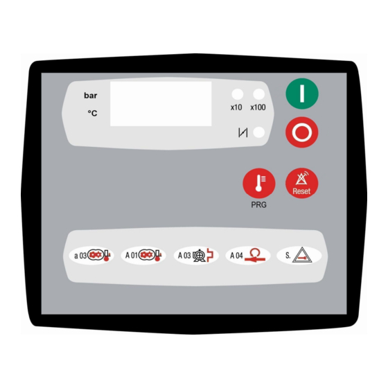
Note! The AirBASIC 2 controller display can only show up to 3 digits. Numbers with 4 or 5 digits are indicated by the illumination of LEDs x10 or x100, which are called 10 multiplying factor and 100 multiplying factor respectively. -
Page 31: Indicator Functions
STEUEREINHEIT AIRBASIC 2 –GEBRAUCHSANWEISUNGEN AIRBASIC 2 CONTROLLER – USER MANUAL 2.5.3. Indicator functions • x10: LED (green) indicates that the 10 multiplying factor is active. • x100: LED (green) indicates that the 100 multiplying factor is active. • ( / ), steadily on: LED (green) indicates load operation mode. - Page 32 STEUEREINHEIT AIRBASIC 2 –GEBRAUCHSANWEISUNGEN AIRBASIC 2 CONTROLLER – USER MANUAL With this feature, the operation of the compressor can be disabled from a remote position in order to prevent unauthorized personnel from starting the compressor with the push buttons on the controller.
-
Page 33: Controlling The Compressor Load/Unload Operation
STEUEREINHEIT AIRBASIC 2 –GEBRAUCHSANWEISUNGEN AIRBASIC 2 CONTROLLER – USER MANUAL 2.7. Controlling the compressor load/unload operation • with pressure switch When the compressor is in load operation, the LED ( / ) on the right hand side of the display lights steadily to indicate that the compressor is running in load mode. -
Page 34: Load And Unload From Remote Contact
STEUEREINHEIT AIRBASIC 2 –GEBRAUCHSANWEISUNGEN AIRBASIC 2 CONTROLLER – USER MANUAL 2.7.1. Load and Unload from remote contact • with pressure switch It’s enough to insert a contact in series to the contact of pressure switch; it’s necessary to set the opening and closing of the remote contact coordinating with the setting of the pressure switch. -
Page 35: Switching Off The Compressor
STEUEREINHEIT AIRBASIC 2 –GEBRAUCHSANWEISUNGEN AIRBASIC 2 CONTROLLER – USER MANUAL 2.8. Switching off the compressor The compressor can be switched off locally pushing the OFF button or remotely opening the start/stop remote contact (if a remote contact is connected to the appropriate terminals). In both cases, when the machine is commanded OFF, the controller de-energizes all the relay outputs controlling the contactors as well as the solenoid valve, thereby causing the compressor to stop in a turn off delay time (parameter P17 –... -
Page 36: Timers
STEUEREINHEIT AIRBASIC 2 –GEBRAUCHSANWEISUNGEN AIRBASIC 2 CONTROLLER – USER MANUAL 3. Timers The AirBASIC2 controller permits to show information about the remaining time before maintenance activity (maintenance timers). Moreover is possible to show the working hours of the compressor ( working timer ). -
Page 37: Resetting Maintenance Timers
STEUEREINHEIT AIRBASIC 2 –GEBRAUCHSANWEISUNGEN AIRBASIC 2 CONTROLLER – USER MANUAL 3.5. Resetting maintenance timers Note! When a maintenance pre-alarm message is manually reset, it will no longer appear as long as the compressor is ON. The pre-alarm is displayed again when the compressor is powered again. -
Page 38: Parameters
STEUEREINHEIT AIRBASIC 2 –GEBRAUCHSANWEISUNGEN AIRBASIC 2 CONTROLLER – USER MANUAL 4. Parameters The controller allows the user to change some parameters as those that determines the operation of the compressor,. The default values for the adjustable parameters are listed in the table on the next page. - Page 39 STEUEREINHEIT AIRBASIC 2 –GEBRAUCHSANWEISUNGEN AIRBASIC 2 CONTROLLER – USER MANUAL The table below contains all the available parameters with their respective symbol, descriptions, units of measurement, possible values and default values. For more detailed description, see "Parameter descriptions" on page 17. The parameters from P01 and P04 are shown only using pressure transducer.
- Page 40 STEUEREINHEIT AIRBASIC 2 –GEBRAUCHSANWEISUNGEN AIRBASIC 2 CONTROLLER – USER MANUAL Air filter maintenance pre-alarm 100 − 9900 1500 1500 hours Oil filter maintenance pre-alarm 100 − 9900 3000 1500 hours Separator filter maintenance pre- 100 − 9900 3000 1500 alarm hours 100 −...
-
Page 41: Parameters Description
STEUEREINHEIT AIRBASIC 2 –GEBRAUCHSANWEISUNGEN AIRBASIC 2 CONTROLLER – USER MANUAL 4.2. Parameters description P01 – High plant pressure alarm • Defines the limit of plant pressure. Over this value, the compressor goes in shutdown fault and a A12 message is shown on the display. - Page 42 STEUEREINHEIT AIRBASIC 2 –GEBRAUCHSANWEISUNGEN AIRBASIC 2 CONTROLLER – USER MANUAL P10- Ventilator switch on temperature threshold • Defines the oil temperature threshold, exceed that, it is activated a command output for a ventilator • In normal conditions, this parameter needs no adjustment.
- Page 43 STEUEREINHEIT AIRBASIC 2 –GEBRAUCHSANWEISUNGEN AIRBASIC 2 CONTROLLER – USER MANUAL P18 - Max restarts per hour • Defines the maximum number of permitted start-ups per hour. Its purpose is to protect the motor from damage. When the set number of restarts is reached, the motor will not stop for the rest of the following hour and the compressor will work without interruption, switching from load to unload and vice versa.
- Page 44 STEUEREINHEIT AIRBASIC 2 –GEBRAUCHSANWEISUNGEN AIRBASIC 2 CONTROLLER – USER MANUAL P26 – Automatic restart status If the automatic restart feature is to be used, it is strongly advised to affix a warning sign by the machine to alert bystanders that the compressor may come back into operation automatically and without prior notice.
- Page 45 STEUEREINHEIT AIRBASIC 2 –GEBRAUCHSANWEISUNGEN AIRBASIC 2 CONTROLLER – USER MANUAL P29 – Input IN5 function • Defines the possibility to program an auxiliary input: P29=0 is not used P29=1 with open contact occurs a pre-alarm with a message a06 on the display...
-
Page 46: Error Management
STEUEREINHEIT AIRBASIC 2 –GEBRAUCHSANWEISUNGEN AIRBASIC 2 CONTROLLER – USER MANUAL 5. Error Management 5.3. Advisory Alarms The advisory alarms alert the user that maintenance is needed, or that certain parameters may be approaching their shutdown level. Advisory alarms can be reset while the compressor is running or stopped by pressing the Reset button. -
Page 47: Shutdown Faults
STEUEREINHEIT AIRBASIC 2 –GEBRAUCHSANWEISUNGEN AIRBASIC 2 CONTROLLER – USER MANUAL 5.4. Shutdown Faults The shutdown faults in the controller are designed to protect the compressor from component failure or extreme environmental conditions. These alarms will stop the compressor and/or inhibit its start-up. To reset an alarm message, eliminate the cause of the concern and press Reset. -
Page 48: Inputs And Outputs
STEUEREINHEIT AIRBASIC 2 –GEBRAUCHSANWEISUNGEN AIRBASIC 2 CONTROLLER – USER MANUAL 6. Inputs and outputs AirBasic2 Inputs and outputs... - Page 49 STEUEREINHEIT AIRBASIC 2 –GEBRAUCHSANWEISUNGEN AIRBASIC 2 CONTROLLER – USER MANUAL Connectors legend Input label Functions Status M1 temperature probe and pressure transducer connector: type 4 poles Combicon 5.08 mm Temperature probe Temperature probe Pressure transducer Pressure transducer M2 power supply connector 12Vca : type 2 poles Combicon 5.08 mm M3 RS232 serial port connector: type 4 poles Combicon 5.08 mm...
- Page 50 STEUEREINHEIT AIRBASIC 2 –GEBRAUCHSANWEISUNGEN AIRBASIC 2 CONTROLLER – USER MANUAL M6 alarm relay connector : type 3 poles Combicon 5.08 mm Relay common Auxiliary alarm relay Energized=Open De-energized=Closed Auxiliary alarm relay Energized=Closed De-energized=Open M7 OUT1 output connector: type screw terminals on the I.C.
-
Page 51: Technical Data
STEUEREINHEIT AIRBASIC 2 –GEBRAUCHSANWEISUNGEN AIRBASIC 2 CONTROLLER – USER MANUAL 7. Technical data Specifications Power supply 12Vac ±10% 50-60Hz min 10VA Note! The controller goes OFF with power failures exceeding 400 ms. Memory Non-volatile for set data, compressor status and operating time data storage. - Page 52 Schneider Druckluft GmbH Ferdinand-Lassalle-Str. 43 +49 (0) 7121 959-0 D-72770 Reutlingen +49 (0) 7121 959-151 info@tts-schneider.com www.schneider-airsystems.com Ersatzteilkatalog / spare parts catalogue / catalogue de pièces de rechange en ligne / catálogo de piezas de recambio / reserveonderdelencatalogus / reservedeler katalog / katalog części zamiennych / pótalkatrész katalógusunkat folyamatosan / katalog náhradních dílů...
Need help?
Do you have a question about the AIRBASIC 2 and is the answer not in the manual?
Questions and answers