Table of Contents

Summary of Contents for Berkley Tool SSHM-2
- Page 1 OWNER’S MANUAL Self-Priming Horizontal Multistage Pump 293 Wright St., Delavan WI 53115 SSHM-2 Installation/Operation/Parts For further operating, installation, or maintenance assistance: Call 1-888-237-5353 BE682 (Rev. 12/3/08) © 2007...
-
Page 2: General Safety
Safety READ AND FOLLOW GENERAL SAFETY SAFETY INSTRUCTIONS! WARNING This is the safety alert symbol. When you see this symbol on your pump or in this manual, look for Hazardous pressure! one of the following signal words and be alert to the Do not run pump against potential for personal injury: closed discharge. -
Page 3: Table Of Contents
Table of Contents Thank you for purchasing a top quality, factory tested pump. Page General Safety .....................2 Warranty ......................3 Installation ......................4-6 Electrical......................6, 7 Operation ......................8 Maintenance ....................9-11 Troubleshooting....................11 Repair Parts .......................12 LIMITED WARRANTY BERKELEY warrants to the original consumer purchaser (“Purchaser” or “You”) of the products listed below, that they will be free from defects in material and workmanship for the Warranty Period shown below. -
Page 4: Warranty
Installation BEFORE YOU INSTALL YOUR PUMP Dirt and Scale Plug Pump and Pipes! NOTICE: Well must not be more than 20' depth to water. 1. Long runs and many fittings increase friction and reduce flow. Locate pump as close to well as possible: use as few elbows and fittings as possible. - Page 5 Installation CASED WELL INSTALLATION Priming plug 1. Inspect foot valve to be sure it works freely. Inspect strainer to be sure it Priming tee is clean. Suction pipe 2. Connect foot valve and strainer to the first length of suction pipe and lower pipe into well.
-
Page 6: Electrical
Installation PUMP INSTALLATION Make sure that all pipe joints in the suction pipe are air tight as well as water tight. If the suction pipe can suck air, the pump will not be able to pull water from the well. 1. -
Page 7: Electrical
Electrical Connection Diagram for Single-Phase Motors Green Your motor’s terminal board (under the motor end cover) should match the Ground diagram in Figure 12A or 12B. Screw For single-phase motors, follow Figure 12A. For 3-phase motors, follow Figure 12B. If motor does not match this picture, follow the connection diagram on the motor nameplate or in the motor connection box. -
Page 8: Operation
Operation PRIMING THE PUMP NOTICE: The term ‘priming’ refers to the process of pumping all the air out of the system, filling the pump and suction piping with water, and begin- ning to move water through the pump and out into the system. A ‘self- priming’... -
Page 9: Maintenance
Maintenance MAINTENANCE If motor is replaced, replace the shaft seal and O-Rings. Keep a seal and O-Rings on hand for future use. Be sure to prime pump before starting. Vent Plug NOTICE: The mechanical shaft seal in the pump is water lubricated and self-adjusting. - Page 10 Maintenance SEAL REMOVAL 1. Follow the instructions under “Pump Disassembly”, above. 2. Remove the discharge pipe from the bracket (Key No. 4). 3. Remove the hold down bolts from the bracket. 4. Turn the bracket motor side up on the bench and use a screwdriver to carefully tap the stationary seal half out of the bracket (see Figure 21).
-
Page 11: Troubleshooting
Maintenance 8. Reinstall the sleeve on the bracket and the pump suction body in the sleeve. Be sure that you do not pinch or damage the O-Ring. See Figure 26. 9. Install four capscrews (Key No. 18) through the pump head and into the bracket. -
Page 12: Repair Parts
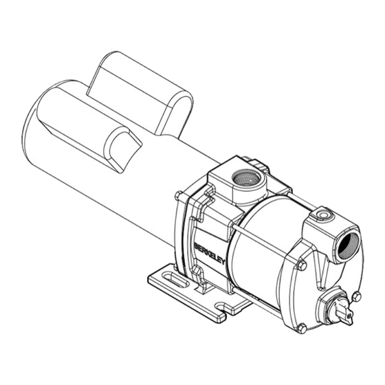
Repair Parts Exploded View B82456 B82639 4311 0203 REPAIR PARTS LIST Part Description Used B82456 B82639 Motor M15087 M14007 Socket Head Capscrew U30-104ZP U30-104ZP Slinger 17351-0009 17351-0009 Bracket M13784 M13784 Impeller Repair Kit B85604 B85604 (Includes Key Nos. 6–8 and 10–14) Shaft Seal* U9-6 U9-6...
Need help?
Do you have a question about the SSHM-2 and is the answer not in the manual?
Questions and answers